;-)
Laughing is it thus apparently not always succeeded to develop a method for the determination of the sound of transistors (and even if only circuit-related), or to stumble on it;-) At least it worked: With a stereo JLH: change all four end transistors;-) Or maybe it was enough, only one per channel. And then listen. Listen to music. And after a while transistor exchange. With quite calm and relaxed. And listen again. Quite relaxed. And always take notes. Not complicated, I hope;-)
... or does it has any sense to talk about e.g. different TO-3 types, if they didn't bring any sound (audire) changes?
If you don't want to do without any "bootstrap", but have heard that a capacitor do terrible things here, put a resistor between emitter and base. Just try;-)
All "biology" is "electrophysics" only;-)-;The man's name is Andrei, he is 31 years old. A director by education, a programmer by profession, he is engaged in the development of computer games. He appointed a meeting in a backyard in the courtyard along Palantaya Street. According to him, this is a favorable place, which is exposed to minimal electromagnetic radiation. At the meeting, he asked to put the phone in airplane mode, and measured the background with his device. Making sure that everything was in order, he told his story...
https://pg12.ru/news/736
Some people are pure detectors. And, I remember: mobile radiation ist THE key technology for the New World Order, not to control and steer only. It is to sanction too, it is a weapon-system:
If you don't get up in the morning, you won't get up again: The identification of individually body-damaging or killing frequencies is done by this technique. Angulation allows to emit indiviually selected frequencies locally in different field strengths. Adieu - also you dear dreaming, soon also "useless people", gouvernement and secret service kids;-)
Marginal but surely better.. so better that you need only one bolt for mounting. Do you really think its not possible to build a nice sounding amplifiers using 2N? If yes then why not with TIP35C? I believe it can be used for low power class-a like JLH & i see no reason to reject it. As a immature nob i'm not going to use MJL3281 for sure which is one of the finest audio transistor available. I have Toshiba C5200 too, i can experiment with those.Better in what way? Sure, TIP35 can deliver more current, handle higher peak loads but how about linearity at 1 amp? Neither type is particulary good but TIP35/36 are not really suitable for good quality audio amplification at all..
Regards
Last edited:
That actually developed when Gates had the idea of adding a dye to the vaccine for use in countries that have no or very poor medical record keeping facilities. Essentially not a bad idea for a variety of reasons.tracking devices that Bill Gates is secreting in the so-called "vaccine".
") They could use dog identification thingies but those don't add tracking or mind control etc and never could even if injected with a hosepipe,
They could use dog identification thingies but those don't add tracking or mind control etc and never could even if injected with a hosepipe,Anyway back on topic.
Selection of the power transistors, We know what the operating currents need to be and might look for transistors with ideal characteristics for that. May find some but they wont handle the power so up the power rating. That might look interesting until SOR is looked at. Ok in class B but not A. The gain characteristics etc may not be perfect but usable, Actual power handling in use is set by the heatsink as well as the part. That need considering as the part is selected,
The small metal can part. Fact of life they will handle more power than plastic equivalent. A part with a tab would be needed for that. It's power handling is a bit more tricky. It's load resistance is there but when it's fully saturated the volts across it are lower. At the other end of the scale the current must be lower. When working on class B outputs there is a factor that can be used based on peak power to get at the actual power dissipation.
I can't remember it. This part though is in class A. The factor must be a sort of DC equivalent of a sine wave in an area under the curve sense. I'm too rusty on this but there will be a factor. There may be a 1 or 2amp power transistor that can replace it. Bolt on but heatsink probably not needed,The other one is a decent through hole part. Ft, gain and etc and may be a lower noise type as that is stated on some makes.
LOL Will it work when you've done it? I doubt if Hood did any really complex maths when he designed it. More select parts on the basis of what they need to do. Bias the circuit and then test it. The biasing sets the gains to some extent and he'd probably have to use typical curves. He also looked physically at part parameter changes to see what effect they had. Data sheets do seem to have deteriorated to me. hfe doesn't seem to exist anymore just HFE. The currents used to test that may give an indication of the range the part is intended to be use at and ft frequencies. Typical usage may be mentioned.
Regarding the sound of transistors, some examples:
Had older SD525. A dream: creamy and fine. Recently bought new ones. Trivial, average in sound.
Had BD139. A dream in terms of voices. So beautifully elaborated and contoured. Bought newer: trivial, average.
KSP44 bought 3 pcs. for testing: Percussion. The wood colors, grains, contours and rhythm brilliant. A week later ordered 20 pieces. New batch and the sound: trivial.
The question of current control in the JLH is an interesting one. The original MJ481 transistor JLH specified was a small chip, low capacitance high fT (at the time back then (4MHz)) device. My now fading datasheet (dated '69) indicates that the gain changes by about +47% between 25 and 175C at 1A. So - if we take the nominal 8 ohm load the operating voltage was 27V at 1.2A. That makes the dissipation in each transistor about 16W. If "room temperature" is allowed to be 50C (and while that seems excessive it is not far off if an amplifier is sitting in direct sunlight) and the junction temperature is kept to 100C that means the total thermal resistance should be 50/16 or 3.125 C/W. The transistor has a thermal resistance of 2C/W, which means the heatsink should be 1.1C/W (without any mica washer, direct mounting, with the insulating problems that brings) per transistor. The drift from 25C to 100C would limit the current change to 24% assuming a linear response. That would mean setting the current to 1A when cold, but obviously you can make some calculations for your own situation and how hot you would allow the junction to become.
Using modern transistors with lower thermal resistances helps, provided the gain change with temperature is known. TIP3055 has a thermal resistance of 1.39K/W but no temp dependence of gain on the datasheeet I have. MJ15003 has a thermal res of 0.7C/W and a gain change of 33% at 1A between 25 and 150 C - the gap closes at higher currents, so would be more stable in a JLH. Neither have the minimum ft of the original (at 3 and 2MHz). I do not know what the fhfe is but it would look like only just surpassing 20kHz if the gain were 100 on the MJ15003, so while it offers more stability and a smaller heatsink (unless you want to increase power) it might not sound as good as the original, but it would be better than the old RCA2N3055.
Thoglette mentioned that he would keep his JLH power supply. That is a good move. It is only a capacitance multiplier, and its current is set, as in the JLH, by the gain of the transistors. Disregarding, for the moment, that the gain of the transistors in the power supply will change with temperature, also depending on the heatsink used, there is an interesting behaviour in the current drawn by the amplifier.
The first point is that as the amplifier warms up, and the quiescent current rises, it demands more current from the power supply. Being fed by a limited gain transistor pair, the voltage will fall and to some extent will oppose the current rise in the amplifier, but of course with a penalty of limiting the peak output power.
As many of you know, the JLH exploits the push-pull arrangement in the output stage to cancel the largely second harmonic distortion each device generates through the gain non-linearity with current. The residual distortion is also partially balancing the second harmonic distortion created by the PNP input transistor which operates at a relatively low current and undergoes a significant current swing at full output. The supply current in the positive wire feeding the amplifier (and this is the 1969 original design I am discussing) will not remain constant, but reflect the average current draw. As the upper output transistor exhibits a significant non-linearity the current actually reduces with full output compared to the quiescent condition. Further, the output transistor dissipation will reduce as power is delivered to the load, and so when in use the transistors will cool down.
That brings me on to the MJ3281 class of transistor. Because the gains are far closer to linearity than the old generation transistors, the average current drawn on load compared with no load is not very different. That would make a simple choke filter even more beneficial. And, as a reminder, in this thread many moons ago I reported simulations showing that the slew rate using these devices is a lot better than any of the 2N3055-type transistors (and I refer to epi base types). Therefore, with the lower distortion, more uniform current draw, and better frequency response I would say that these should perform better than those older transistors.
Finally, that raises the question of how best to stabilise these against oscillation. A Tian probe (in simulation)showed that the basic design was stable even when not compensated - that implies that instability reported by many (including myself) could be related to layout and decoupling as the response extends into the tens of MHz. I have suggested a solution to the instability problem. A challenge, I think, is to develop a scheme which works well - but, and this is a big caveat - does not degrade the performance of the amplifier in the audio spectrum. I suggest that JLH's alternative stability components is not one I would recommend.
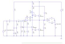
And here is my proposal.
Nothing novel in the compensation scheme. It uses phase lead correction, together with resistors in series with the base of the output transistors acting as "sprog stoppers". An input network provides a degree of protection against slew rate limiting distortion, with a 47 ohm load to makes sure this is resistive at high frequencies. On the output I have added a Zobel network which is probably not essential but recommended to reduce stray pickup from leads etc. at high frequencies. It's a true Zobel in that the capacitor and inductor operate at the same frequency (1.6MHz) so as to not burden the output stages beyond their limit as many networks add another parallel load, but it will mean careful layout still. Don't skimp on the 10nF Zobel capacitor - use a high current type for low impedance. I've seen "any old capacitor" get quite hot in some circuits.
All the electrolytics are large values to improve LF response.
The bias potentiometer has to pass up to 20mA for lowest gain transistors and should therefore be a 1W type even though it should not dissipate more than 400mW.
Depending on the models of transistor used, it offers half to one fifth of the distortion simulated with older TIP3055 type devices at 10kHz, the best figure being 0.05%, at 8W into 8 ohms. Distortion naturally reduces at lower outputs.
Caveats: only simulated. Simulations may not include quasi-saturation so the distortion near full output might be higher. To offset this use a higher voltage power supply (36V) and increase the heatsink accordingly.
I might even build this to test it!
P.S.- the input resistor is only there for simulation testing. Recommend 100k for real not 1k. And add a 1k resistor on the output side of the capacitor, both to provide pull-downs for biasing in the event that inputs and outputs are not connected.
Attachments
Last edited:
I would not recommend JLH's solution because the 1nF feedback capacitor is large and creates a small problem, but the real culprit is the 1nF and 100 ohm on the base of the driver transistor. That really kills the gain in the PNP input transistor, which is operating at a low current and will lead to cutting off for a fast input signal. Adding a resistor in series with the feedback capacitor corrects the phase at high frequencies, and the sprog stopper resistors become useful when using high speed transistors.
But you are welcome to try JLH's solution if you prefer.
But you are welcome to try JLH's solution if you prefer.
Ok go back to his original article and a comment about what sets the output voltage. No standing current adjustment - what does the dc and ac feedback do?
He tries different gain arrangements on the output transistors. As the best figure matches his main graph at 9w he is likely to have done all at 9w but the problem is still likely to be the mismatch. He also says
and for the lowest possible distortion with any pair, the voltage
at the point from which the loudspeaker is fed should be
adjusted so that it is within 0.25 volt of half the supply line
potential. The other results are summarized in Table 2.
but doesn't say how. The bias point of the input transistor could be changed. Later it looks like he shows 2 resistor values in that chain. I think these bias values extend the LF. I have no other info on this one, Or have and haven't really looked at it.

The top transistor is effectively working as an emitter follower - performance some what different to the other that is driving via it's collector.
This is the 25 years later circuit but 15w and split supplies

I've not really taken much notice of that one. The principles are similar but a quick look showed a report that may have less detail than the original 10w one.
He tries different gain arrangements on the output transistors. As the best figure matches his main graph at 9w he is likely to have done all at 9w but the problem is still likely to be the mismatch. He also says
and for the lowest possible distortion with any pair, the voltage
at the point from which the loudspeaker is fed should be
adjusted so that it is within 0.25 volt of half the supply line
potential. The other results are summarized in Table 2.
but doesn't say how. The bias point of the input transistor could be changed. Later it looks like he shows 2 resistor values in that chain. I think these bias values extend the LF. I have no other info on this one,
Or have and haven't really looked at it.The top transistor is effectively working as an emitter follower - performance some what different to the other that is driving via it's collector.
This is the 25 years later circuit but 15w and split supplies
I've not really taken much notice of that one. The principles are similar but a quick look showed a report that may have less detail than the original 10w one.
In another article he points out it doesn't do the transient response much good - think it's the AB amp that on that score doesn't match the original 10w in that respect but power dissipation is a lot lower. There was an interesting letter later from some one about transistors used in AB that pointed out flaws.That really kills the gain in the PNP input transistor,
Setting the centre rail voltage is quite a simple matter of replacing R8 (in the original circuit) with a 22k resistor and series 47k pot to trim it. Chinese kits I think provide something like that. The reason that was important is because the current in the resistors in the collector of the drive transistor then conducts the optimum base current needed by the output transistors. If the centre rail is offset, the output transistor currents will either become limited or the dissipation will be higher than necessary. Seems to me to be a power issue as much as distortion. I would usually recommend setting the centre rail for symmetrical clipping for maximum power.
(A bootstrapped emitter follower is not really an emitter follower as the drive impedance to it is increased. That has the effect of making it operate more or less as a common emitter amplifier, though with bootstrapped resistors the impedance on the base is whatever the bootstrapped resistor value is. For lower gain transistors that has to be lower, which increases the parallel current to the base and increases distortion).
Simulations suggest that there is marginally lower distortion if the centre rail is slightly higher than midpoint, but it is very marginal.
My concern with JLH's direct coupled design is that, as I mentioned earlier, the non-linearity in the transistors available at the time alter the average current through them between no signal and full load. His constant current arrangement references the current in the collector of the upper output transistor. Since that changes with loading, there is scope for some current adjustment occurring after a signal burst, which may limit the output dynamically. I suggest it would have been better to have had a more standard CCS.
Perhaps you or your local supplier, are now buying from China, where specifications are historical and part numbers mean very little. Almost every semiconductor is a poor copy or substitute for something else. This does keep costs and prices very low but this is for kids, beginners or just practicing your soldering technique.Regarding the sound of transistors, some examples:
Had older SD525. A dream: creamy and fine. Recently bought new ones. Trivial, average in sound.....
Last edited:
- Home
- Amplifiers
- Solid State
- JLH 10 Watt class A amplifier