JLH1969 is simple BJT four transistor A-class amplifier designed by John Linsley Hood in 1969 (UK),in some way it resemble Williamson tube amp architecture,
but in my humble opinion it is more close to Julius Futterman OTL amp architecture , if is made properly is very good sounding amp , originally uses obsolete two Motorola MJ480 but 2N3055 is very good substitute , faster modern power BJT`s lead this simple amp into heavy instability .
RE: LOL! Brand new Krell for $175. Man, those pirates are ballsy! - Banat - Amp/Preamp Asylum
OFF: The Julius Futterman Story and the eternal art of good circuit design.
The Julius Futterman Story
Last edited:
Below the original John Linsley-Hood’s Class-A power amp design, as you can see it is very simple and it employs only 4 transistors. OTL was a fact! This kind of amp finds its roots in the end of the 1950's. In the 1960's and later these amps were quite common. The advantage compared to earlier designs is de DC coupling of the stages and the OTL final stage. A huge improvement in sound quality as it turned out.
amplifiers
amplifiers
Go ahead without looking back ")
New time, new ideas, new experience.
High quality laid by John Lindsley-Hood originally.
But there is always room for improvement.
2n3055 is a family of GP transistors from different manufacturers (sometimes better, sometimes worse). MJ15003 is better according to many reviews. 5200 is very good, but taking into account the peculiarities (possible instability). Other options are also possible (MJ802). Perhaps the use of MOSFET.
Last edited:
Go ahead without looking back
New time, new ideas, new experience.
High quality laid by John Lindsley-Hood originally.
But there is always room for improvement.
2n3055 is a family of GP transistors from different manufacturers (sometimes better, sometimes worse). MJ15003 is better according to many reviews. 5200 is very good, but taking into account the peculiarities (possible instability). Other options are also possible (MJ802). Perhaps the use of MOSFET.
There are certainly better transistors around now than the venerable 2N3055 but given the current in the 8ohm version of the JLH 10W is only 1.2A and Vce is only about 15volts it’s not exactly being stressed, it more important you pick a higher gain matched pair 2N3055 than go for exotic high speed transistors that burst into flames spouting Latin as soon as a taxi goes past.
I found this very interesting Doubtless others saw it. As has been said before faster transistors due to lower capacitance could be a good idea. Test equipment required.
Class A amplifier kit - fixing the distortion problem - YouTube
Class A amplifier kit - fixing the distortion problem - YouTube
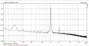
today i measured my JLH with EMU (24V @ 1.2A BC560 + BD139 + BD911(matched) ) - not bad - attached picture for 1W @ 8 ohm dummy load.
Clean up to about 6-7W in audio range ... then begins the harmonic "forest" ... below 1W THD approx. 0.007%. 50Hz Noise are high from my measurement "setup".
I don't know if any update to win10 solved it - but suddenly my EMU USB started working
Clean up to about 6-7W in audio range ... then begins the harmonic "forest" ... below 1W THD approx. 0.007%. 50Hz Noise are high from my measurement "setup".
I don't know if any update to win10 solved it - but suddenly my EMU USB started working
Attachments
There were a few direct coupled JLH. The massive advantage with capacitor coupling is it offers DC protection with no complex circuitry added on. I also find a capacitor has to be of very low quality to ruin the sound. I would imagine few these days are that bad. A modest capacitor might outperform an output transformer of a respected tube design like Dynaco. Of all the problems the world has the JLH output capacitor isn't one. I would use Panasonic FC types made up to the value. Very low cost and very good.
I have heard a capacitor coupled OTL tube amp by Croft. It was wonderfully open and fast. Tube Cad has ideas for that and many transistor amps. JLH I seem to remember also.
I have heard a capacitor coupled OTL tube amp by Croft. It was wonderfully open and fast. Tube Cad has ideas for that and many transistor amps. JLH I seem to remember also.
Thanks for posting that, Nigel! I am working with a pair of boards just like that.
Don't fit the lead capacitor put a low pass filter on the input - or include that in the pre-amp it can be a 6dB/Octave at the input or with a nfb loop.
The modular pre-amp designed for this had active low pass filtering 18dB/Octave ( unfashionable nowadays except in digital source hardware)
6dB/Octave is good enough.
I'm looking at the 1969 article in which JLH says under the heading "Stability, power output and load impedance" - " the author has not found any combination of L and C which makes the system unstable, although the system will become oscillatory with an inductive load if R3 is shunted by a small condenser to cause roll of at high frequencies"
R3 is the 2k7 feedback resistor.
There may be some misunderstanding about fitting a phase lead capacitor on the JLH. I agree that JLH said that the "system will become oscillatory" but so will other designs if the capacitance is large. When JLH made that comment he might have been thinking about using such a capacitor to limit the frequency response of his circuit once he realised its bandwidth was higher than originally thought. If a large capacitor is added, the phase shifts it causes can lead to instability. By large, we're talking about capacitances in the region of 100pF or more. For example a 220pF capacitor across 2.7k will give a -3dB at 267kHz. And cause oscillations in simulation, so almost certainly in practice.
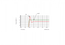
A small capacitor on the other hand is stable in a Tian probe with 90 degree phase margin and better than 30dB gain margin, using 2SC5200's. It might be better to have a larger margin. So it seems to me that a small capacitor is acceptable and I have used 33pF successfully with a speaker (inductance) attached without problems. Compared with a "bare" 2SC5200 which had a phase margin of 70 degrees and gain margin of 20dB.
However that should be stable, but with less margin.
Another problem with a phase lead capacitor is that the UGF is higher. So that might be an issue with feedback if wiring and layout are unsuitable. Filtering the input won't change the stability issues unless the input conditions are improved by the addition. The input impedance to the first transistor may be problematic with some preamps as the JLH input impedance was high. A high input impedance from the preamp will cause the input transistor frequency response to fall - and that may cause unwanted phase shifts which may mean adding a phase lead causes problems.
I haven't exhaustively investigated this but those are some of the issues I have uncovered.
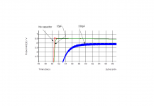
Nigel- interesting video. Somehwere buried in this thread is one of my posts showing the simulation results of rise time of an old 3055 (the 2N3773 was worse, though, and I think the presenter might have chosen that deliberately - I'd never have used a 3773 in an audio amp, but did use them for a high power power supply once) compared with an epi 3055 which tied with the 2N3716 but all were beaten by a 2SC5200 or MJL3281A.
Diagram is for MJL3281A andy_c model with 200uH-5ohm dummy load.
A small capacitor on the other hand is stable in a Tian probe with 90 degree phase margin and better than 30dB gain margin, using 2SC5200's. It might be better to have a larger margin. So it seems to me that a small capacitor is acceptable and I have used 33pF successfully with a speaker (inductance) attached without problems. Compared with a "bare" 2SC5200 which had a phase margin of 70 degrees and gain margin of 20dB.
However that should be stable, but with less margin.
Another problem with a phase lead capacitor is that the UGF is higher. So that might be an issue with feedback if wiring and layout are unsuitable. Filtering the input won't change the stability issues unless the input conditions are improved by the addition. The input impedance to the first transistor may be problematic with some preamps as the JLH input impedance was high. A high input impedance from the preamp will cause the input transistor frequency response to fall - and that may cause unwanted phase shifts which may mean adding a phase lead causes problems.
I haven't exhaustively investigated this but those are some of the issues I have uncovered.
Nigel- interesting video. Somehwere buried in this thread is one of my posts showing the simulation results of rise time of an old 3055 (the 2N3773 was worse, though, and I think the presenter might have chosen that deliberately - I'd never have used a 3773 in an audio amp, but did use them for a high power power supply once) compared with an epi 3055 which tied with the 2N3716 but all were beaten by a 2SC5200 or MJL3281A.
Diagram is for MJL3281A andy_c model with 200uH-5ohm dummy load.
Attachments
Last edited:
"If the output impedance of the pre-amplifier is more than a few thousand ohms, the input stage of the amplifier should be modified to include a simple f.e.t. source follower circuit, as shown in Fig. 8. This increases the harmonic distortion to about 0.12%, and is therefore (theoretically) a less attractive solution than a better pre-amplifier." Simple Class A Amplifier
There may be some misunderstanding about fitting a phase lead capacitor on the JLH. I agree that JLH said that the "system will become oscillatory" but so will other designs if the capacitance is large. When JLH made that comment he might have been thinking about using such a capacitor to limit the frequency response of his circuit once he realised its bandwidth was higher than originally thought. If a large capacitor is added, the phase shifts it causes can lead to instability. By large, we're talking about capacitances in the region of 100pF or more. For example a 220pF capacitor across 2.7k will give a -3dB at 267kHz. And cause oscillations in simulation, so almost certainly in practice.
A small capacitor on the other hand is stable in a Tian probe with 90 degree phase margin and better than 30dB gain margin, using 2SC5200's. It might be better to have a larger margin. So it seems to me that a small capacitor is acceptable and I have used 33pF successfully with a speaker (inductance) attached without problems. Compared with a "bare" 2SC5200 which had a phase margin of 70 degrees and gain margin of 20dB.
However that should be stable, but with less margin.
Another problem with a phase lead capacitor is that the UGF is higher. So that might be an issue with feedback if wiring and layout are unsuitable. Filtering the input won't change the stability issues unless the input conditions are improved by the addition. The input impedance to the first transistor may be problematic with some preamps as the JLH input impedance was high. A high input impedance from the preamp will cause the input transistor frequency response to fall - and that may cause unwanted phase shifts which may mean adding a phase lead causes problems.
I haven't exhaustively investigated this but those are some of the issues I have uncovered.
Nigel- interesting video. Somehwere buried in this thread is one of my posts showing the simulation results of rise time of an old 3055 (the 2N3773 was worse, though, and I think the presenter might have chosen that deliberately - I'd never have used a 3773 in an audio amp, but did use them for a high power power supply once) compared with an epi 3055 which tied with the 2N3716 but all were beaten by a 2SC5200 or MJL3281A.
Diagram is for MJL3281A andy_c model with 200uH-5ohm dummy load.
The fT of a 2N3773 is 200kHz - lower than a tenth of that of a 2N3055. JLH did not use lead capacitors in any of his audio designs - the impedance of capacitors decreases with increasing frequency so the path for spurious signals in the environment is more likely to penetrate through to the inverting input. JLH took the dominant pole capacitor from the collector of the Vas transistor and connected the other end to the inverting input.
Bob Cordell advises against using lead capacitors in the feedback in general although some time ago he described the circumstances where exceptions could be made. It was not as simple as calculating the values of R and C for a desired roll off frequency. I think this was on the long thread dealing with his book within the last two years.
Quite so. Which is why I'd never use one in an audio amp and said it was worse than the 2N3055. I just didn't think it necessary to quote the numbers to make the point.The fT of a 2N3773 is 200kHz
JLH took the dominant pole capacitor from the collector of the Vas transistor and connected the other end to the inverting input.
Er.. that's phase lead. Just not from the output.
And if some wish to use a large capacitor to limit the frequency response, then taking the capacitor from the collector of the VAS works if a phase limiting resistor is also connected in series. Value 100-220 ohms or around there.
That is what my comment applied to. I said that you cannot just use a large capacitor. But my point was that that may have been exactly what JLH was commenting on, on the basis that capacitors of 220-330pF or thereabouts would have been required to limit the frequency response to 200kHz. Or thereabouts.It was not as simple as calculating the values of R and C for a desired roll off frequency.
Last edited:
Re "phase lead just not from the input" of late that technique has been defined as "Miller Inclusive Compensation" MIC for short - see Miller Inclusive Compensation (MIC) Design Example which quotes from Cordell giving fresh information to consider.
The earliest example I can think of MIC is the Bailey amplifier published in Wireless World in the sixties. Nelson Pass also used this in early BJT Class A amplifier DIY projects.
The earliest example I can think of MIC is the Bailey amplifier published in Wireless World in the sixties. Nelson Pass also used this in early BJT Class A amplifier DIY projects.
The only thing that surprised me about the Quad 405 is that it could make the 2N3773 usable. I would have loved to try Exicon FETs in a 405. Reason being that these FET never completely switch off at 0V bias. This wouldn't be about speed. The Quad 303 which is a distant cousin of JLH is a better amplifier to my ears than 405. 303 class AB sounding like Class A and measuring like it.
- Home
- Amplifiers
- Solid State
- JLH 10 Watt class A amplifier