mini1969=JLH1969 (mod)
1. You can use different transistors.
2. This is a complete circuit, except for the discrepancy between the power of the resistors R6 and R7 and the original (not enough).
3. I would supply power (and ground) from the output transistor side. Grounding the speaker there. Leave the input (signal ground) as it is.
4. Put a jumper on C1. Try different capacitors outside the board.
Zero Zone
Carefully. There is a mod N-P-N and P-N-P.
Other PCBs have no advantage
Last edited:
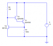
I had in mind a simple circuit to power a device. You can probably find resistors to suit. This one simulates at 7A in the test device (Tr1) with the models used.
Circuit is not critical, almost any suitable transistors can be used eg TP41 for the driver, and the current limiter. 2N3055s tend to have high gains around 100-500mA so can provide useful drive for (even higher) power devices.
Measuring semiconductor capacitances has one caveat: the AC voltage has to be small or the device could become forward biased (at a DC voltage of zero). That can have two problems: first, the impedance becomes low (may upset the result) and second, the capacitance is actually quite large (diffusion capacitance adds to the depletion capacitance). Typically, industrial measurements are made with 10mV (rms). My capacitance meter generates 100mV (rms) but that just about works for silicon devices, I would not trust it on germanium. (at least not with an additional reverse bias). (Not that I've got many germaniums now. A few which aren't in use any more, in "long term storage").
Yes, you can use a 1M resistor and larger (non-electrolytic) cap eg 100nF to isolate the DC from the AC measurement.
You need to check what your DMM uses to measure capacitance.
Attachments
Last edited:
I was thinking of TTC004 as I was writing...so, as the newest driver types from Toshiba, why not give them a try with the proviso that they may be a bit too fast. If you can check this, look for signs of oscillation at supersonic frequencies up to 1 MHz.
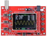
Well I never bought a real oscilloscope for home. I have several Arduino based ones that I built but those top out at 1MSPS.
I do have the little oscilloscope shown in the attached photo. I will try that. My experience looking for oscillation mainly involves spectrum analyzers on RF amplifiers. So should I just look for a sharp versus fuzzy/broadened output waveform with say 10 kHz input sine wave? Should I input a 10 kHz square wave and look for ringing?
Attachments
I had in mind a simple circuit to power a device. You can probably find resistors to suit. This one simulates at 7A in the test device (Tr1) with the models used.
Circuit is not critical, almost any suitable transistors can be used eg TP41 for the driver, and the current limiter. 2N3055s tend to have high gains around 100-500mA so can provide useful drive for (even higher) power devices.
That reminds me of a Darlington booster with current limit to boost the current capabilities of a three terminal regulator.
I should be able to build that easily with spare parts from repairing amplifiers. So I think that passes the test of using parts readily available to other DIYers who might want to provide measurements from their own real versus fake output transistors.
Measuring semiconductor capacitances has one caveat: the AC voltage has to be small or the device could become forward biased (at a DC voltage of zero). That can have two problems: first, the impedance becomes low (may upset the result) and second, the capacitance is actually quite large (diffusion capacitance adds to the depletion capacitance). Typically, industrial measurements are made with 10mV (rms). My capacitance meter generates 100mV (rms) but that just about works for silicon devices, I would not trust it on germanium. (at least not with an additional reverse bias). (Not that I've got many germaniums now. A few which aren't in use any more, in "long term storage").
Yes, you can use a 1M resistor and larger (non-electrolytic) cap eg 100nF to isolate the DC from the AC measurement.
You need to check what your DMM uses to measure capacitance.
Well my capacitance meters are integrators. (One is the popular M328 transistor tester and the other is my own ATMEGA16 based design.) No HP/Agilent 4278A at home.
The current limiting transistor should be separate from the test transistor and ideally not dissipate much power, or is adequately heatsunk, so that its base voltage is stable. The base current of the test transistor can be measured with an ammeter between the driver emitter and base.
To measure the temperature of the device you need a thermocouple mounted as close to the metal tab of the device as possible. If the tab is accessible when mounted (TO-218/ TO-220 for example) that would be a good place for it. If it is only a surface plate (TO-264 etc) then you could either mount the thermocouple directly under it on the opposite side of the heatsink, or possibly, drill a small hole though the sink to allow the thermocouple to contact the metal plate (but that will change the thermal resistance a bit!). There should be direct contact between the transistor being tested and the heatsink, ideally zero degrees per watt, but you may get 0.1 using thermal compound (or these days a graphite film).
I guess you have arduino projects, or A DMM, which can measure temperature with thermocouples.
Integrators are fine too, if the voltage is limited. What voltage range do they work on?
No, I've not got one of those either. Though my little meter is hand-holdable.
Last edited:
mini1969=JLH1969 (mod)
1. You can use different transistors.
2. This is a complete circuit, except for the discrepancy between the power of the resistors R6 and R7 and the original (not enough).
3. I would supply power (and ground) from the output transistor side. Grounding the speaker there. Leave the input (signal ground) as it is.
4. Put a jumper on C1. Try different capacitors outside the board.
This morning I soldered a 12000 uF 35V Nichicon LS capacitor directly to the leads of the output transistors. The negative was soldered to the emitter of the lower NPN transistor using 2 inches of 16 AWG stranded copper. The positive was soldered to the collector of the upper NPN transistor using 4 inches of 16 AWG stranded copper. (As close as I can get.)
The power supply was then connected to the 12000 uF 35V Nichicon LS capacitor through a 0.12 Ohm current sense resistor (on the negative lead) and a 10D-11 NTC inrush limiter (on the positive lead).
With the current sense resistor installed I was able to measure and adjust the bias. Both are now set to 1.0A (at 24 degrees C) and both increased to 1.1A after one hour. The bias was originally 1.1A for the side with 2SC5198 outputs and 0.4A for the side with TIP35C outputs. This has now been corrected with the aid of the current sense resistor.
The supply is 24V. Is 1.0A a suitable bias? What do you recommend for 24V supply and 8 Ohm speakers?
After one hour of listening the heatsink increased in temperature from 25.4 degrees C to 55.0 degrees C. So with 48W of dissipation the heatsink increased 29.4 degrees C or about 0.62 degrees C per Watt. That is my best heatsink outside of the defunct Onkyo TX-SR707 which has a much larger heatsink.
And yes, I think the sound has improved with the power supply capacitor, wiring and biasing changes. It sounds great on things like vocals and piano (on one of my favorite test CDs) and it is now much improved but not great for louder/denser mixes (like hard rock). The bias was too low on the TIP35C side.
Next I can look at the driver transistor.
With the TIP35C and 2SC5198 outputs I am considering getting a 36V supply. Any comments/suggestions/warnings about moving to a 36V supply with 8 Ohm speakers? Recommendations on bias current with 36V? 1.5A? Higher? Lower?
Last edited:
I guess you have arduino projects, or A DMM, which can measure temperature with thermocouples.
I have an Arduino project that measures with thermistors and another for platinum RTD.
I do have a little Ebay purchased hand held K type thermocouple meter along with a bead type probe.
Integrators are fine too, if the voltage is limited. What voltage range do they work on?
I built that a few years ago but from memory I used 63% of Vcc (5V) as the threshold. I could adjust it to 10% of Vcc (0.5V) with more noise or even 5% (0.25V) but I am not sure I want to go much lower. I suppose I could go lower and use an LM358 to amplify the output of the integrator to make a lower voltage design. I could try going lower without the LM358 and see what happens.
5198 Collector power dissipation, no more: 100 W\20*C.
Therefore, no more than 30v / 1.2a. You won't hear a difference of a few watts. Overheating problems will be.
The bias current is adjusted by decreasing R7 (not to 0!). We need transistors with Hfe = 100\1a or more.
Amplifier for quiet evening listening
Therefore, no more than 30v / 1.2a. You won't hear a difference of a few watts. Overheating problems will be.
The bias current is adjusted by decreasing R7 (not to 0!). We need transistors with Hfe = 100\1a or more.
Amplifier for quiet evening listening
The heatsinks required to dissipate the extra power as you scale up the bias and voltage become a problem when you consider how much power you can get from the amplifier. JLH'69 in its standard form, requires about 32V and 1.25A bias current to comfortably drive an 8 ohm speaker with TO3 power transistors like 2N3055 for 10W RMS output. Modern speakers are not what they seem either and they aren't rated the same way as in the past. They're actually lower impedance than the nominal ratings suggest and will need more drive current, hence bias too.
So you may need to adjust the supply voltage and bias current appropriately. I wouldn't exceed the scope of the tables with a single pair of TO3P transistors, though. With the basic setup, a stereo amplifier will need a heatsink of less than 0.5K/Watt rating which is becoming pretty big, expensive and still gets toasty in warm weather.
Tables 1 and 3 in the original Wireless World article, detail the recommended supply and bias currents according to your speakers. They address the speaker efficiencies and impedances of the day, which are a little different now and what may be labelled a nominal 8 ohms will now be more like 6. However, the article is a good read as well as informative and essential if you want to wrap your head around the design and requirements. There's a lot more to read about it and later mods at The Class A Amplifier Site archive. If anyone hasn't seen it yet, it's hosted by Rod Elliott of ESP: The Class-A Amplifier Site
Re: the oscillation/stability issues: Yes, square wave testing shows up instability as waveform distortions like overshoot and evidence of HF oscillation as fuzzyness but you need a 'scope to see it and it's likely to be difficult to interpret the results properly without some experience of correlating the observed waveforms with known problems of different types/designs of amplifier.
Last edited:
I was thinking of TTC004 as I was writing...so, as the newest driver types from Toshiba, why not give them a try with the proviso that they may be a bit too fast. If you can check this, look for signs of oscillation at supersonic frequencies up to 1 MHz.
If I try the TTC004 (especially with the 2SC5198 outputs) should I add a small base collector capacitor to be safe?
Especially if no one else has tried the TTC004 with 2SC5198 or 2SC5200 outputs? Has anyone had to do with with any of the faster drivers?
I guess I am safer on the other amp/side which has two TIP35C devices.
Ian, you referred to the original JLH article, but I would point out that the values seem to be very close to ideal. Most modern transistors exhibit quasi-saturation (discussed already so I summarise) which means a lower gain at low C-E voltages. Since the drive current in the original design is fixed by the bootstrap resistors, that means either the voltage has to be increased (so the transistors don't go into q-s) or the bias current (to provide extra drive). Either way increases the static dissipation, and depends on the q-s behaviour of the chosen output devices.
Hi,
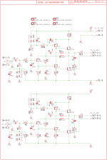
I came across this JLH HPA sch on The Class-A Amplifier Site - JLH Headphone Amplifiers website. has anyone built it?
Also any suggestions regarding sizing of resistors and setting up?
regards
prasi
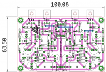
PS Rough layout is attached, for reference of packages used.
I came across this JLH HPA sch on The Class-A Amplifier Site - JLH Headphone Amplifiers website. has anyone built it?
Also any suggestions regarding sizing of resistors and setting up?
regards
prasi
PS Rough layout is attached, for reference of packages used.
Attachments
Last edited:
I'm not sure exactly what you mean by the "the values" there. I presume you mean that it's JLH's tabled values that seem to be very close to ideal, so they don't need altering.Ian, you referred to the original JLH article, but I would point out that the values seem to be very close to ideal....
If so, I wouldn't argue since that was assumed when I posted the reference but if the OP wants to experiment further with more supply voltage for more power, I think the efforts still have to fit within the tables' options. On reading my post again, I imagine it appears to say that you can just increase whatever you like to suit your needs but that wasn't my intention.
Did I address your concern there, or I have I lost the plot?
Maybe I misunderstood, but I thought you referred to the table of volts and currents for different loads. (I should have followed the link to check).
All I was suggesting (well, my intention) was that those values (if I have interpreted your comment correctly) may not give the lowest distortion possible near clipping when the transistor voltages get near saturation, because of a reduced gain through quasi-saturation. In other words, the amplifier may prematurely clip.
Depending on the nature of the output devices used, it may need some increase in volts to avoid that, or current, but just raising the current will lead to higher distortion near clipping due to the reduced gain anyway, so I'd recommend considering playing with the volts rather than the amps. It may only need a couple of volts increase, and it maybe a not very important effect, but I thought I'd bring it to peoples' attnetion.
Hmm, a 5 transistor JLH? I don't think you want to get involved with that design as there are a few HPA designs that follow the original JLH design and you wouldn't enjoy having to defend this particular variation unless you had compared it with one similar to the original, yourself.Hi,
I came across this JLH HPA sch on The Class-A Amplifier Site - JLH Headphone
Thanks John, I see the point you are making and fair comment.....All I was suggesting (well, my intention) was that those values (if I have interpreted your comment correctly) may not give the lowest distortion possible near clipping when the transistor voltages get near saturation, because of a reduced gain through quasi-saturation.
- Home
- Amplifiers
- Solid State
- JLH 10 Watt class A amplifier