The 2sc seems more equilibrated... Now with the 2N i have a ton of gain, more mids and punchier bass. Now i can hear each and every tone of bass individually. As for the hights, well, now i have hights sufficiently to hear everything. Very good transistor. I wasnt expecting this. The 2n shines. The mids are very clear, dynamic and with allot of presence.
You are right Mjona, each stage, and amp has its own suitable transistor with its characteristics and parameters accordint to what the designer has in its mind.
Even tough the 2sc5171 has better Cob, and parameters, its just TOO MUCH for this little fellow jlh. It seems the 2SC5171 its just a better choice for the Hiraga 30 watter emitor follower topology than this one.
THanks
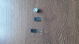
Next: the bd139-16 from ST (SGS Thomson).
You are right Mjona, each stage, and amp has its own suitable transistor with its characteristics and parameters accordint to what the designer has in its mind.
Even tough the 2sc5171 has better Cob, and parameters, its just TOO MUCH for this little fellow jlh. It seems the 2SC5171 its just a better choice for the Hiraga 30 watter emitor follower topology than this one.
THanks
Next: the bd139-16 from ST (SGS Thomson).
Last edited:
The bd139-16 from ST: the bass is a bit less punchier but deeper at lower lewels and less detailled ( they are still there but you need to concentrate more to distinguish them on "Almost home, melosense remix" and "sounds from the ground--tending the wine") with less nuances, a less cleaner overall sound at max level, with a bit of heard distorsions on "the shadow of your smile by Jacintah" (a sign of saturation?). The bass flattens a bit at max level and so the mids. Less presence on "what a difference a day makes--chantal chamberland" and the sound is less present in "Mantovani-moon river|.
The hights are still there but less crisp wich makes the amp a bit less revealling. The mids are a tiny bit more softer on the trompets on the "smoke gets in you eyes by chantal chamberland", and "Take five by Dave Brubeck".
The hights are still there but less crisp wich makes the amp a bit less revealling. The mids are a tiny bit more softer on the trompets on the "smoke gets in you eyes by chantal chamberland", and "Take five by Dave Brubeck".
Attachments
Last edited:
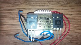
Next, a nos 2sc3611 by Panasonic, from the monkey box. ")
Now THIS is something, this driver gives the deepest, thoughest, punciest bass from them all, a verry verry close match to the Hiraga overall sound and IS an amp with an input and output cap!!!!! (and i use cheap industriall ones!!!---i have to dig in more into this aspect to fine tune this aspect)
I think that the bass deffinetly has something to do with the Cob of only just 3pf @1mhz, because in the Hiraga i have a ton of caps, blodly matching transistors etc etc etc to listen to something like this........ This is very interesting that the 300mhz Ft doesnt care that much.
The mids are very close to the Hiragas, very present, full, clean with no distorsion or signs of saturation at max power. The hights are clean, clear and revealing but less sharper in the upper end compared to the 2N.
This overall combo makes a very natural, present and pleasant overall sound.
Now i have a ton of gain as with the 2N but even cleaner and clearer, richer and full of details as it should be.
I think that the receipt for this amps Vas is a transistor of 50mhz or more, very little Cob and noise, no more than 1.2-1.3w max max and at least 60V to coup with the psu and voltage swings.
Hard decision to make... I have to do more listening to decide and buy more 2N and 2SC is i can find..
Last edited:
In post 5455 in reply to Nigel Pearson I made a comment about what he described as an "imbalanced" LTP structure where the collector resistors were 8.2k and 180k and a reference to the Naim 250 amplifier where I said this does not help in a Class A amplifier if the harmonic structure is monotonic.
Sorry about that Nigel - looking through some older simulations I have actually tried this in a simulation which gave good results which may be of interest to you and perhaps huggygood as well.
This does have quite high power dissipation but less than the 1996 circuit which I built. Still my most recent interest has been in a simplified conventional LTP version that has even less dissipation - about half that of the 1996 circuit.
When it comes to an actual build I have to sit down and work out a pcb layout by hand and frequently other more pressing demands get in the way while time moves on and I am content enough with my 1996 amplifier in the meantime.
The proof of a simulation is an actual build but I will post the details of the simulation on a notional basis.
Mjona, are you an amp designer? If yes thanks for the detailled explanations. But when "the outcome of this modulation process is a loss of current gain (and a recovery on the reverse cycle)" the transistor saturates and starts clipping like the bd139 in my case or cuts off?
I read wiki abit and tried to understand what is with the b,c,e regions and how they decrease and increase, do they expand like dilatations from heating?
I read wiki abit and tried to understand what is with the b,c,e regions and how they decrease and increase, do they expand like dilatations from heating?
coooooool !!
For cooler running I would limit the supply rails to +/- 22Volts which is the point I started out with the simulation I am posting. The idea to use MJL3281 super beta output transistors was to reduce the current demand on the split phase transistor - a 2N5551 in this instance.
This is rated variously at 625 m.W. (or 1W in an old Motorola Small Signal Databook) I have a couple of Motorola 2N5551's in my old stocks. In the simulations here the median dissipation is about half of the lower figure.
There is a version of this device where the collector and emitter leads are crooked out to fit wider track spacing. This allows the pads on the copper side of a pcb to be a little larger. In theory some of the heat in the body of the transistor will travel down through the leads into the copper of the pcb.
If dissipation in this transistor becomes an issue with a requirement for high output current levels then 2SC 3503 or KSC 3503 would give a close enough result.
The latter and 2N5551 are not available over the counter in electronics stores and there are no major warehouse suppliers where I live. Some of these will sell only in minimum quantities like 200 which I regard as a turn off.
There is another option use a 2N3904 and cut down on the output current and power level to a little bit more than the 1969 Class A which should be adequate with reasonably sensitive speakers and more than enough with some of the larger and more sensitive ones.
The simulation attached is to determine the stability margins. In this R5 and R14 need to be variable for adjusting dc offset and output current. R10 connects to the negative rail rather than earth. The intention here is to allow a thermal cut out to be mounted on a heat sink to turn the amplifier off if it gets too hot - or otherwise if the negative rail fails the constant current sources will be disabled and avoid a dc fault on the output line.
To run the simulation copy the expression in blue on the .asc file i.e. -1/(1-1/(2*(I(Vi)@1*V(x)@2-V(x)@1*I(Vi)@2)+V(x)@1+I(Vi)@2)) right click to run and click on vout. In the .raw file the expression V (vout) will show in the title header. Right click on this and delete that and paste in the expression copied as above.
In the attached cursor box select the option for cursor 1 and 2. Drag cursor one horizontal as close as you can to 0 dB and use the left and right arrow keys on your keyboard to make fine adjustments. Repeat this exercise with cursor 2 and drag this as close as possible to - 180 degrees and use the arrow keys to make fine adjustments.
The gain and phase margins are shown in the box at the bottom. A phase margin of 45 degrees is about the minimum however simulations are predictions which don't take account of stray capacitance and variations in transistors. Alterations in phase start a decade in frequency in advance of the point where gain has declined by 3dB you should be able to check this using the cursors.
Attachments
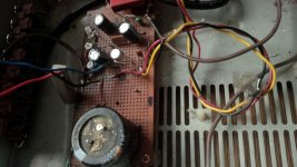
A couple of years back, I think about 10 by now, I had readed tens of times the Hiraga philosophy about the 20w classe a. Somewhere in that article he sayed something about floating ground for amps with output caps..
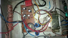
Made the jlh69 and didnt try till now. After seeing mr Kokoriantz Sublimed jlh I had to gave it a try, and what do you know. I dont need snake oil caps on the output to make this amp shine..I made a floating ground - and equilibrated the output to 0v with a dummy load hooked up, and what do you know, the amp is stagerring right now. Just incredible!!!!!!! I can confirm each and every word Kokoriantz sayed. I have hear such hights only in my Hiraga. They are plenty,crisp, clear and doesnt iritate. They just got silk smooth. Incredible!!!!
The mids are just like those heard at a friend of mine on his SET 300b. Stagerring I tell you!!! Fine, detailled,full, round, precise and present.. What to say more??
The bass, well here I need more caps. Now I have only two pieces of 3300uf in series, but will buy bigger ones because it doesnt go that low like when I had 6600uf as I got used to.. I dont even need to bypass these suckers with smaller ones. They are enough. On a fullrange speaker this combo rips your jaw off your face. Incredible!! Thanks KoKoriantz for the ideea to test this. I will test your variant too.
Ps: I think this ideea of floating ground is good too because, in either way,double psu (+-) or float, if an output burns it takes the speaker with it. So a protection is mandatory in either case.
Attachments

Last edited:
Thanks Mjona. I will try the sim tomorrow. Now its a bit late here in RO.
One more thing intrigues me, with the 2sc video trasistor, it oscilates if I have under 1.5A bias if I go up no problem, only with the heat...
Neither of the other transistors did this, I could go as low as 500mA with the 2n1711. Why is this? How can I counter this? Spliting the 1k2 bias resistor in two to protect the upper transistor base and decresing the upper resistor of 150R to half to acomodate to the bigger demands of this transistor? Also I gained a bit more hum with the video 2sc and even more with the floating ground.. does this fellow need some compensation C-B of lets say 40-60pF?
Thanks in advance
Sergiu
Mjona, are you an amp designer? If yes thanks for the detailled explanations. But when "the outcome of this modulation process is a loss of current gain (and a recovery on the reverse cycle)" the transistor saturates and starts clipping like the bd139 in my case or cuts off?
I read wiki abit and tried to understand what is with the b,c,e regions and how they decrease and increase, do they expand like dilatations from heating?
I am just and enthusiast like the majority of people who participate and share their thoughts.
Early effect has a relatively small impact on transistor gain in general. It becomes more important when you try to minimize distortion at high frequency where one transistor type can give a slightly better result. According to Groner in a common emitter amplifier the bases are covered adequately if the standing current is 6 m.a. or more.
Although Linsley - Hood deplored using a capacitor between the collector and base of the main gain transistor, this has the effect of swamping the inherent capacitance in the transistor diffusion which is subject to variation under dynamic conditions.
There is a snag with this in that a common emitter stage inverts the signal and so the total capacitance internal and external is multiplied by the gain of the stage and this appears as a load on the input of the stage which the main input transistor has to drive.
Taking the compensation capacitor to the inverting LTP transistor base avoids the main problem another way to deal with this suggested initially by Self is to include a buffer transistor between the LTP and the main Vas transistor.
The maximum current you can expect from your amplifier is about twice the standing amount you decide on, so if the load demands more than this the amplifier will head more into distortion and at the extreme limit it will clip.
From your description of what is happening I think this is the cause.
With regard to the effects of heat on transistors, the simplest explanation is this works to loosen the bonds which keep electrons attached within the crystalline structures which more frees electrons allowing more current to flow.
Specification sheets quantify current gain at room temperature 25 degrees C. The gain is inversely proportionate to the temperature on the Kelvin scale of 298.15 degrees.
THD simulation
The THD simulation is shown here. I have reinstated the passive input filter which corrects the dc offset present in the Tian simulation. I bypassed this to get a truer indication of the stability margins due to the active part of the circuit.
There is only one emitter resistor for the output stage, Q4 in combination with Q6 acts as a constant current source for the phase split transistor and to feed Q9. The combination of R12,Q6,Q9, and R14 resemble the equivalent of the lower half of a conventional quasi complementary layout.
Q6,Q9, and Q10 should share the same heat sink. If a Q7 a 2N5551 is replaced by an alternative, check the stability margin in the Tian plot simulation with the same substitution.
Attachments
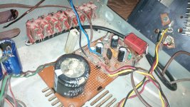
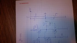
I tested it Kokorianz. The voice is rounder, and a tiny bit cleaner, the bass is more profound, deeper and punchier...The bootstrap circuit as seen has two problems to resolve .
The shunt resistor needs to be 250 ohm for best frequency responce of the upper output transistor.
The pull up resistor is loading the output too heavily pumping 12% from its power and polluting the PS .
The remedy I will try out in compliance with 1969 technology , is to supply the bias current by a choke . 1H/50ma can be sufficient , but its resistance should be less than 30 ohm . The choke must be small enough to be installed upon the heatsink adapter mounted by the same screws joining the heatsink .
I will go DIY mode and wind it myself . I'll report about it in few months .
The hights are now even more silk smooth like but not sharp like before. It still needs some tweaking. Nice adition though.
Thanks
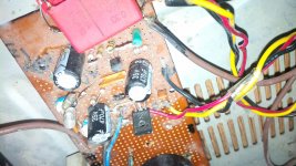
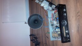
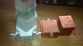
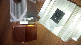
I fitted new rads from xeon servers for the higher gain outputs. Will test them this week.
Happy new year to all! And enjoy good quality music in this new year!
Cheers
Sergiu
Happy new year to all! And enjoy good quality music in this new year!
Cheers
Sergiu
Attachments
- Home
- Amplifiers
- Solid State
- JLH 10 Watt class A amplifier