Is it posible you removed the input capacitor by mistake ( wrong side )? I notice you refered to the volume pot.
The little green cap is input... seems OK.
The volume nob was removed from input, so now it's direct source to input.
did you cut the link before measuring 1A?
Made the link after measuring.
bi polar i thinkIs it posible you removed the input capacitor by mistake ( wrong side )? I notice you refered to the volume pot.
why not .Check the input transistor
it's a 2sc2240 bl on this kit
ZEROZONE Assembeod V18 PNP Sanken 2SA1216 JLH1969 classe Un power amp conseil 10 W + 10 W L4 45 dans Amplificateur de Electronique sur AliExpress.com | Alibaba Group
I think this is a PNP output version?
The Vcc rail should be -20.4V?
The mid point should be -10.2V. I assume you mean it only gets to -9.1V.
What is the current in the input transistor (measure the voltage across the feedback resistor).
Should be around 400-500uA.
If looks OK then suggest just reducing the (fixed) resistor connecting the input base to - rail. DOn't know what values you are using but if say it is 100k, adding an 820k across it will reduce it to 90k and may just allow the voltage to reach -10.2V. Suspect your low voltage PSU is causing this limit to the potentiometer range.
The distortion you hear may be due to oscillation. Make sure the input is connected to a low impedance load to test the amplifier, if not try a small capacitor (e.g. 100pF) to ground (from the input base).
You can almost totally swamp this "high" fb resistor issue with closing the loop around the speaker (so around the output cap) and using a low-R resistor pair there - like 270R + 22R. This will make things different.
Yes this would be possible, but it is a law of diminishing returns. The input transistor current is biased at about 0.5mA, so has an emitter impedance of about 50 ohms. The 220 ohms resistor therefore reduces the OLG by some 5x that could be had. I suggest an optimum would be 47 ohms and 560 ohms because the downside is that a lower emitter resistor increases the bandwidth - and hence gain at high frequencies, potentially leading to lower stability or oscillation. That would increase the OLG by some 2.5x and hence reduce THD by 2.5x.
I would not recommend connecting this to the speaker- keep it on the centre rail. Speaker feedback will give LF phase shifts that may be unwelcome too. Modern capacitors with low ESR and ESL should be good, certainly better than the old types. Would be interested if anyone has THD measurements on them.
It would be interesting to do a version of the Naim LTP for the JLH. I only think this worthwhile as the 0V or mid volts is absolutely ridged which helps set the standing current.
Don't add degeneration to the the LTP emitters without doing a listening test. It makes a Naim LTP idea near impossible. What you could do is unequal emitter resistors. One advantage although small is the Naim input stage has slightly more current for the working arm. This is of no importance really, just an observation.
If you think a LTP and output capacitor a worthless idea think again. TDA2030 etc can run that way and it offers DC protection. TDA has a LTP input. It is possible that some may like the JLH because it has an output capacitor. I would speculate that this quality is retained even when > 10 000 uF. It's getting as near to DC as possible whilst not being DC. This can give a more open sound. All the capacitors can be tuned by ear. Forget everything you have ever read about capacitors. Mostly the right value matters far more than the " quality ". As Julian Vereker pointed out to me the demands of modern devices ( computers, SMPS ) has changed all capacitors for the better. He said the NAP250 had improved sound wise with no new technical input from him. It just happened. That sort of contradicts what I just said. My point is get the sound as you like it, then buy speacial parts. Panasonic FC types are cheap and very good.
My brother who alas isn't here now said he noticed from repairing amplifers the best sounding often had very different time constants in the amplifer. That is some trouble had been taken to get it right. Use some cheap speakers when doing first tests to be sure nothing is wrong when trying ideas. Simon's point was no two time constants should be the same. Even 2Hz will be different enough. 1Hz 3Hz 5Hz 7Hz, something like that. BTW. When my brother died I had to learn these things all over as he did all my technical work. Luckilly I had done the studies and had always taken an interest. He was a first class house builder also. This was a weird combination as he was at the PHD level in electronics. He never drove a car.
The first recorded use of LTP in the UK was a Cavendish amplifier or so it's said. It was AC coupled. Some say they are all copies of an RCA design. Not really true and the Naim certainly not. The uA741 more likely and the other the Sinclair Z30 about the time of the JLH. The Sinclair was fragile as it used driver transistors as outputs. These being fast worked well. A+R A60 was a very reliable version using the faster for the time TIP3055.
JLH by 1980 had returned to single input transistor. This is worth saying as he mostly introduced the LTP to amplifier design for ametures. He in his very quiet way hinted he prefered it. LTP is easier so he wouldn't have rejected it without a good reason. His 1980 amplifer completely rejects all the Folk Law of then and now. Using devices and topology known to be troublesome he had no trouble at all. He quietly said how the amplifer was made stable and in passing said why he rejected usual thinking. That being the so called " Blameless " type. The 1969 JLH has " Blameless " compromises. Being class A it is not really a problem as the output stage is always conducting. If anyone has a SIM it would be interesting to qualifiy that.
Possibly your late brother might have been using a golden ratio set of -3 dB low frequency turnover points - refer Fibonacci number - Wikipedia.
There is a tendency to use larger values of electrolytic capacitor than strictly necessary - to lower the internal equivalent resistance making use of low ESR types widely used in switch mode power supplies.
JLH commented about this in the Everyday and Practical Electronic series of articles in September 1993 ( I referred to this series in an earlier post but omitted "Everyday" - sorry about that.)
In this he said Rx a term he used for the non -linear element he described as being likely to be voltage, temperature, polarity, and frequency dependent, and even being influenced by the shape of the a.c. waveform applied to it.
Where used to block dc to earth in the lower feedback arm of a divider network this was said to have so small effect on THD measured at say 1kHz.
However when it comes to intermodulation distortion the real - life imperfections are more easily seen.
For that you need a good signal generator and a spectrum analyser - to demonstrate why one electrolytic capacitor might sound better than another.
One potential source of distortion in a capacitor I came across was that of parametric changes. I have not investigated further yet, but old (1980) capacitors used in a 50W AC coupled amplifier sing when the output current reaches about 2 or 3A. That can only be due to the electric charge on the plates causing physical movement (like an electrostatic speaker). That undoubtedly causes distortion, but I have not heard modern low ESR/ESL units make a noise. The distortion of the output signal from that amplifier was 0.02% at 1kHz, so even with the capacitor joining in with the speakers, it was not a huge issue at the time.
Nigel
Linsley Hood may have been thinking of the old type of phase splitter used in valve circuits when he designed the 10Watter. A triode or transistor with equal collector (anode) and emitter (cathode) resistors will give approximately equal output voltages but opposite in phase. Morgan Jones called this circuit "accordion". The only difference is that JLH uses current rather than voltage.
Linsley Hood may have been thinking of the old type of phase splitter used in valve circuits when he designed the 10Watter. A triode or transistor with equal collector (anode) and emitter (cathode) resistors will give approximately equal output voltages but opposite in phase. Morgan Jones called this circuit "accordion". The only difference is that JLH uses current rather than voltage.
I'll take it apart again when I get some free time, but in the meantime I've attached the schematic.
Additional notes/observations on JLH 1969 first test vs the ACA amp:
1.- The ACA amp sounded warmer and IMO nicer.
2.- The JLH seems to pick up input interference from the power cable, whereas I didn't notice any from ACA.
3.- JLH produces >2x as much heat.
4.- JLH current AC 15.3v@1.8A from the transformer, ACA from memory was ~1A.
5.- No audio from the preamp was audible on the ACA amp while off, whereas the JLH has a lot of audio which sound "broken" and then when the amp turns on just gets amplified.
6.- The Sanken 2SA1216 weighed 18.6grs, and had textured back plate metal... so I assume they're real.
Thanks for all your comments")
Additional notes/observations on JLH 1969 first test vs the ACA amp:
1.- The ACA amp sounded warmer and IMO nicer.
2.- The JLH seems to pick up input interference from the power cable, whereas I didn't notice any from ACA.
3.- JLH produces >2x as much heat.
4.- JLH current AC 15.3v@1.8A from the transformer, ACA from memory was ~1A.
5.- No audio from the preamp was audible on the ACA amp while off, whereas the JLH has a lot of audio which sound "broken" and then when the amp turns on just gets amplified.
6.- The Sanken 2SA1216 weighed 18.6grs, and had textured back plate metal... so I assume they're real.
Thanks for all your comments
Attachments
I think more and more that you have a real problem with your jlh.
after, it's not easy to compare one amp with another but I do not have
found point of comparison between the ACA and the JLH, I found the ACA too "soft"
and the voices back from the jlh and he descended less into the bass.
I gave it to a friend.
if you have a transistormetre, I advise you to disassemble your pcb and test everything.
TTL logic had that same type totem pole outputs. Supposedly in 60's....
Linsley Hood may have been thinking of the old type of phase splitter used in valve circuits when he designed the 10Watter.
...
I'll take it apart again when I get some free time, but in the meantime I've attached the schematic.
I've not seen the PNP version before so I am interested in how you are going.
I ran the supplied .pdf circuit into LTSpice and got the following*:
250 ohm to bias at 1Amp.
Max potentiometer value of 100K yields balance voltage at 9.6ish volts.
Maximum voltage in before clipping: 0.75v
THD @1khz = 1.5% into 8 Ohms
THD @1khz = 2.4% into 4 Ohms
Harmonics are predominantly Odd into 8 Ohm, Even into 4 ohm.
---------------------------------
What impedance are your speakers?
I can't decipher what the value of C30 is. Can you please tell me so I can update the model?
The distortion figures seem quite high compared to similar NPN models I have run and the one I built.
--------------------------------
* Disclaimer: I am in no way an expert in running sims or repairing audio circuits. I have most undoubtedly made some mistake or other in the sim but I'm here to learn and any escaping smoke is down to the owner.
Last edited:
Distortion seems high, suspect too near clipping.
Thanks diyaudio - SPICE models for the devices found on these threads!
Simulation at 23V supply, 10V peak into 8 ohms 0.08% at 1kHz.
Data sheet shows slight decrease in gain at below 2V for 2A current, hence with approx. 11.5V per side I limited the output to 10V peak, 8 ohms.
Comparison with NPN (2N3055 (epi)) output THD at 10W (30V supply) 0.24%
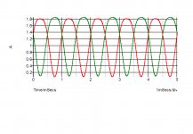
Transistor currents illustrated for 3055. 22% distortion, mostly 2nd harmonic, in each!
Thanks diyaudio - SPICE models for the devices found on these threads!
Simulation at 23V supply, 10V peak into 8 ohms 0.08% at 1kHz.
Data sheet shows slight decrease in gain at below 2V for 2A current, hence with approx. 11.5V per side I limited the output to 10V peak, 8 ohms.
Comparison with NPN (2N3055 (epi)) output THD at 10W (30V supply) 0.24%
Transistor currents illustrated for 3055. 22% distortion, mostly 2nd harmonic, in each!
Attachments
Nigel
Linsley Hood may have been thinking of the old type of phase splitter used in valve circuits when he designed the 10Watter. A triode or transistor with equal collector (anode) and emitter (cathode) resistors will give approximately equal output voltages but opposite in phase. Morgan Jones called this circuit "accordion". The only difference is that JLH uses current rather than voltage.
According to JLH in his book "Valve and Transistor Amplifiers" the idea of the split load phase stage was suggested by Williamson (and used in his Classic valve amplifier).
Most of the valve designs in JLH's book (including his own) use Long Tail Pairs to split phase.
The Baxandall low cost 5 W amplifier ( Wireless World issue in March 1957 pp108-113.) is an exception which used only three valves - these a dual ECC81 a pair package with one half serving as the input and the other as a split-load phase splitter driving a pair of EL84's.
If ever there was a valve amplifier that resembles the 1969 Class A amplifier in terms of simplicity and function, albeit in solid state technology, I think we can be more specific about whose earlier work influenced JLH's thinking.
We should Baxandall in particular and also Williamson.
Greetings to everyone!
I also had the audacity to look for an improvement of my JLH (2005): simply carrying out an "upgrade" of the final transistors passing from MJ15003G to MJ21194G more "modern" and theoretically with better characteristics. I thought in an improvement of the already good results that the amp offers: so it was NOT. In practice the sound aspect has been disappointing; the amplifier has lost its personality, the ability to deal with authoritative signals has been lost, the result is a faint and feeble sound. This, though remaining with the same regulations used in the use of mj15003g. Analyzing the situation accordingly, the big negative difference that leapt to the eye was a noticeable difference of Hfe 50 versus 70 of the old, the other parameters all seem to improve. So I thought, having available a number of MJ21194, try to pair a pair in the Darlington configuration, but after reassembling everything I saw that this type of assembly made me burn the 5A fuse that I put to protect the supply trastormator. At this point I think I'm not able to make any further changes so I would like to ask someone who is able to use the simulators if it were not possible to try to perform a simulation test with the above mentioned modification, to check what can be the causes of the dangerous outcome found. Unfortunately I do not have any knowledge of the simulation tools and if someone lent themselves to the experiment, I think it could be something of common interest. I think it is useful to include the scheme of the circuit in question and I want to clarify that the supply voltage is + -20V and a bias of about 1.5A for each single pair of BJT outputs. I hope someone can help me to continue the experiments, assuming that we can achieve some positive results. Thank you. Greetings!
Mleod
- Home
- Amplifiers
- Solid State
- JLH 10 Watt class A amplifier