Does the photo you posted happen to be a 500/5 you have in the shop currently or is it an old photo? My other inductor in this amp is also burnt up now that I've looked at it a bit closer. Would rewinding it get me close enough to the correct uH valve to determine a core material?
I have several sets of 500/5 photos. One of them may be from one of the 500/5s I have in the shop. I'm trying to get some data for someone else on another amp. If I get time later today, I'll disassemble one of the amps and try to get the value. I'll also measure the wire diameter.
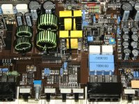
I was able to get a measurement on a small portion of wire that wasn't completely blackened and crispy. It looked to be about .51mm in diameter so I believe that to be equivalent to 24AWG. Sadly I do not have any of that on hand. However it will be near impossible to judge what the insulation thickness on the wire was because it is all burned off. I would imagine the insulation layer on this type of wire should be negligible for this application.
Would a NEMA MW 35-C rated 24awg wire be suitable for this? Not sure how warm these should get during normal operating conditions.
Would a NEMA MW 35-C rated 24awg wire be suitable for this? Not sure how warm these should get during normal operating conditions.
Disregard the measured values that I posted previously. My LCR meter appears to be badly out of calibration for inductance. I'm going to try to borrow one. If I cannot, I'll drive a high-frequency signal through the inductors and calculate the inductance.
There is no magnet wire that will be damaged by the heat produced by normal operation. Low temp wire is 'solder strippable'. High temp wire has to be stripped mechanically (possibly chemically but I don't know of any chemicals that melt the high-temp insulation).
There is no magnet wire that will be damaged by the heat produced by normal operation. Low temp wire is 'solder strippable'. High temp wire has to be stripped mechanically (possibly chemically but I don't know of any chemicals that melt the high-temp insulation).
Perry, in your experience with the JL amps would the bias voltage being too low cause the amp to have unequal rail voltage? I clamped the 4 channel side to a heat sink and adjust the bias voltage and was going to see if that part of the amp was able to produce clean audio. In adjusting I measured the rail voltages and they seem to have balanced out at +-33 volts for the front channel. Just wondering if maybe there is a short somewhere that in handling it has done something to move the voltages more equal or if the bias voltage could really impact the rails that much?
before bias adjustment the front channel rail was around +40 and -27 volts, the rear channel was right at +-25 volts, bias measured around .0002 volts on all channels. Wish all the JL amps stuck with the little two pin header to measure the voltage. No worries about probe slip. With the bias pot turned up near the approximate location i've seen it on the other JL amps the bias is set around .004 volts and the rails on the front channel are pretty near equal at the +-33 volts. The output sounds pretty clean to my ears on all 4 channels of this amp. Guess it would be handy to have a scope to confirm the signal coming out is good.
on the 500/5 is there an opamp that can be bridge like on the 500/1 to check the drive signal at the outputs? I'm working on a parts list so I can try and capture everything in one order. The outputs and power supply of the subwoofer section all seem to check out ok as far as not failed from what i'm able to test. However it would be nice to check that the drive signal is appearing where it should. I'm still not sure what caused the inductors and output caps to burn up along with a few other smaller capacitors near the outputs.
I'm concerned that there is a problem either with the meter or the points where you are measuring the voltage. In just the last few amps you've repaired, you've had more uneven rail voltage than I have in all the time that I've been doing this work.
I can't remember jumping an op-amp in the 500/5. With no outputs in the class D circuit, if you pulse the remote, it should give you drive signals on the output transistors.
I can't remember jumping an op-amp in the 500/5. With no outputs in the class D circuit, if you pulse the remote, it should give you drive signals on the output transistors.
On this amp I did use both of the meters I have available to measure the rail voltages at the diode output leg, the inductors and at the output transistors themselves. I was getting the same skewed values using both meters until the bias voltage was raised near the 4mv range. I would agree that previously I did attempt measurements in places that were not reasonable to measure which made for some incorrect readings with the meter I was using.
I went back to the amp and turned the bias pots back down for all channels and it does indeed cause the voltage to change from +-33.2 when the bias is at .004v to +40, -27 when they are turned full CCW. from now on I'll be sure to check the bias voltage before asking about rail voltage. Thanks again for your help. I would assume this is probably somewhat normal for them to float up as you mentioned when the bias is set so low.
I went back to the amp and turned the bias pots back down for all channels and it does indeed cause the voltage to change from +-33.2 when the bias is at .004v to +40, -27 when they are turned full CCW. from now on I'll be sure to check the bias voltage before asking about rail voltage. Thanks again for your help. I would assume this is probably somewhat normal for them to float up as you mentioned when the bias is set so low.
- Status
- This old topic is closed. If you want to reopen this topic, contact a moderator using the "Report Post" button.
- Home
- General Interest
- Car Audio
- JL Audio Output Inductor