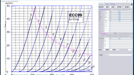
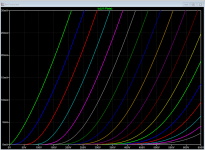
Try my brand new ecc99 model based on JJ datasheet, as for 6sn7 I can remodel using same paint tool for consistency.
Code:
**** ECC99 ******************************************
* Created on 12/25/2018 12:51 using paint_kit.jar 3.1
* [url=http://www.dmitrynizh.com/tubeparams_image.htm]Model Paint Tools: Trace Tube Parameters over Plate Curves, Interactively[/url]
* Plate Curves image file: ecc99.png
* Data source link:
*----------------------------------------------------------------------------------
.SUBCKT ECC99 1 2 3 ; Plate Grid Cathode
+ PARAMS: CCG=5.8P  CGP=5.1P CCP=0.91P RGI=2000
+ MU=23.6 KG1=437.25 KP=170 KVB=224.7 VCT=0 EX=1.484
* Vp_MAX=400 Ip_MAX=50 Vg_step=2 Vg_start=0 Vg_count=11
* Rp=4000 Vg_ac=55 P_max=5 Vg_qui=-48 Vp_qui=300
* X_MIN=125 Y_MIN=37 X_SIZE=922 Y_SIZE=761 FSZ_X=1533 FSZ_Y=882 XYGrid=false
* showLoadLine=n showIp=y isDHT=n isPP=n isAsymPP=n showDissipLimit=y
* showIg1=n gridLevel2=n isInputSnapped=n
* XYProjections=n harmonicPlot=n dissipPlot=n
*----------------------------------------------------------------------------------
E1 7 0 VALUE={V(1,3)/KP*LOG(1+EXP(KP*(1/MU+(VCT+V(2,3))/SQRT(KVB+V(1,3)*V(1,3)))))}
RE1 7 0 1G  ; TO AVOID FLOATING NODES
G1 1 3 VALUE={(PWR(V(7),EX)+PWRS(V(7),EX))/KG1}
RCP 1 3 1G   ; TO AVOID FLOATING NODES
C1 2 3 {CCG} ; CATHODE-GRID
C2 2 1 {CGP} ; GRID=PLATE
C3 1 3 {CCP} ; CATHODE-PLATE
D3 5 3 DX ; POSITIVE GRID CURRENT
R1 2 5 {RGI} ; POSITIVE GRID CURRENT
.MODEL DX D(IS=1N RS=1 CJO=10PF TT=1N)
.ENDS
*$
Attachments
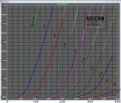
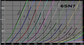
Here is my brand new RCA 6sn7, which also traced quite well with JJ 6sn7 ( curve is a little kinky):
Code:
**** 6SN7_RCA ******************************************
* Created on 12/25/2018 18:04 using paint_kit.jar 3.1
* [URL="http://www.dmitrynizh.com/tubeparams_image.htm"]Model Paint Tools: Trace Tube Parameters over Plate Curves, Interactively[/URL]
* Plate Curves image file: 6sn7-rca.png
* Data source link:
*----------------------------------------------------------------------------------
.SUBCKT 6SN7_RCA 1 2 3 ; Plate Grid Cathode
+ PARAMS: CCG=2.6P  CGP=3.8P CCP=0.7P RGI=2000
+ MU=22.25 KG1=1357.2 KP=135.52 KVB=2040.32 VCT=0 EX=1.341
* Vp_MAX=650 Ip_MAX=30 Vg_step=2 Vg_start=0 Vg_count=18
* Rp=4000 Vg_ac=55 P_max=5 Vg_qui=-48 Vp_qui=300
* X_MIN=33 Y_MIN=37 X_SIZE=1081 Y_SIZE=637 FSZ_X=1550 FSZ_Y=878 XYGrid=false
* showLoadLine=n showIp=y isDHT=n isPP=n isAsymPP=n showDissipLimit=y
* showIg1=n gridLevel2=n isInputSnapped=n
* XYProjections=n harmonicPlot=n dissipPlot=n
*----------------------------------------------------------------------------------
E1 7 0 VALUE={V(1,3)/KP*LOG(1+EXP(KP*(1/MU+(VCT+V(2,3))/SQRT(KVB+V(1,3)*V(1,3)))))}
RE1 7 0 1G  ; TO AVOID FLOATING NODES
G1 1 3 VALUE={(PWR(V(7),EX)+PWRS(V(7),EX))/KG1}
RCP 1 3 1G   ; TO AVOID FLOATING NODES
C1 2 3 {CCG} ; CATHODE-GRID
C2 2 1 {CGP} ; GRID=PLATE
C3 1 3 {CCP} ; CATHODE-PLATE
D3 5 3 DX ; POSITIVE GRID CURRENT
R1 2 5 {RGI} ; POSITIVE GRID CURRENT
.MODEL DX D(IS=1N RS=1 CJO=10PF TT=1N)
.ENDS
*$
Attachments
Last edited:
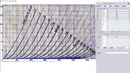
6sn7_rca model, left V scale top Ia 30mA was a little off, sorry about that here is the minor correction:
Code:
**** 6SN7_RCA ******************************************
* Created on 12/25/2018 20:22 using paint_kit.jar 3.1
* [url=http://www.dmitrynizh.com/tubeparams_image.htm]Model Paint Tools: Trace Tube Parameters over Plate Curves, Interactively[/url]
* Plate Curves image file: 6sn7-rca.png
* Data source link:
*----------------------------------------------------------------------------------
.SUBCKT 6SN7_RCA 1 2 3 ; Plate Grid Cathode
+ PARAMS: CCG=2.6P  CGP=3.8P CCP=0.7P RGI=2000
+ MU=22.25 KG1=1315.94 KP=136.88 KVB=1979.11 VCT=0 EX=1.341
* Vp_MAX=650 Ip_MAX=30 Vg_step=2 Vg_start=0 Vg_count=18
* Rp=4000 Vg_ac=55 P_max=5 Vg_qui=-48 Vp_qui=300
* X_MIN=33 Y_MIN=55 X_SIZE=1081 Y_SIZE=619 FSZ_X=1550 FSZ_Y=878 XYGrid=false
* showLoadLine=n showIp=y isDHT=n isPP=n isAsymPP=n showDissipLimit=y
* showIg1=n gridLevel2=n isInputSnapped=n
* XYProjections=n harmonicPlot=n dissipPlot=n
*----------------------------------------------------------------------------------
E1 7 0 VALUE={V(1,3)/KP*LOG(1+EXP(KP*(1/MU+(VCT+V(2,3))/SQRT(KVB+V(1,3)*V(1,3)))))}
RE1 7 0 1G  ; TO AVOID FLOATING NODES
G1 1 3 VALUE={(PWR(V(7),EX)+PWRS(V(7),EX))/KG1}
RCP 1 3 1G   ; TO AVOID FLOATING NODES
C1 2 3 {CCG} ; CATHODE-GRID
C2 2 1 {CGP} ; GRID=PLATE
C3 1 3 {CCP} ; CATHODE-PLATE
D3 5 3 DX ; POSITIVE GRID CURRENT
R1 2 5 {RGI} ; POSITIVE GRID CURRENT
.MODEL DX D(IS=1N RS=1 CJO=10PF TT=1N)
.ENDS
*$As for all models ; they represent an ideal tube, "boogie", what you will get from the vendor will most likely differ. Connecting a real ecc99 ( or a few) in the intended circuit and measure "in real life" might give a better hint.
A single tube don't say the whole story, practical amps contains more tubes and components, it is the total amp that will enter your ears.
A single tube don't say the whole story, practical amps contains more tubes and components, it is the total amp that will enter your ears.
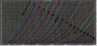
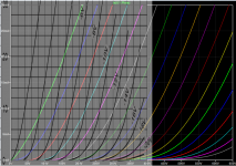
To explain the diff. in distortion depends on the loadline, When the loadline is stiffer say below10k, ecc99 is clearly the winner, but as loadline becomes more horizontal, distortion of 6sn7 leads ecc99 by a bit margin. You see more clearly by looking at the 2 curves attached (color being 6sn7). ecc99 has stiffer curve than 6sn7, but Vg spacing is not as good, esp. when anode voltage is over 350V
Attachments
")
Point taken!
One should not think all tubes of a given type is similar, therefor the amp must be designed to cope with "not-so-perfect" components. Careful design, well away from limits , negative feedback and defensive design are steps on the road.
A distortion figure from simulation only is less important then measurement on a live tube in a mock-up. But neither is sufficient to create a good amp, maybe a step on the road. Then the real question is : "how does it sound with real speakers " ?
- Status
- This old topic is closed. If you want to reopen this topic, contact a moderator using the "Report Post" button.
- Home
- Amplifiers
- Tubes / Valves
- JJ Tesla ECC99 spice model