I've used that circuit with two mods - instead of the resistors I used two CL60 themistors in series. I found that the dc voltage was high and if I can remember correctly I put a 24V zener across the relay. It has been working now for 3 month without an issue. Check that nothing is connected to earth.
What caps are you using?
Hi do you means the caps after the brige? I used the ones supply with the kit.
Do you mean replacing the 470k resistors with the CL60 thermistors? How do you put the 24V zener across the relay?. I have check and there is no earth connection. Apparently more than 200kits been sold and am i the only one ran into trouble?
quan
Don't muck about with mains components if you don't understand the operation. And clearly you don't understand.
Your safest option is to put these back on the shelf until you have negotiated a solution with your retailer.
Understand it totally Andrew. I do like to learn as well. I am waiting for responses from the vendor.
quan
Clearly you don't understand !Hi do you means the caps after the brige? .................
Do you mean replacing the 470k resistors with the CL60 thermistors?................. How do you put the 24V zener across the relay?. I have check and there is no earth connection............
The value of the series resistor and the time it is in series needs to be balanced.
I developed my own version of the softstart and did a lot of measurements to arrive at the best values.
Main proplem was finding values that delivered a steady startup current as well as not burning the resistors.
If the delay is too short you get a "double hump" of inrush current.
If the delay is too long...smoke.
Too many ohms...big secondary inrush.
Too few ohms... too much inrush.
I ended up using 60 ohms (3 x 180ohm/5W in parallel) and 150mS.
Has worked a treat in handling 100,000 uF. The transformer size is not the main issue...it is the duration of the "short" presented by the caps on powerup.
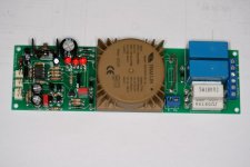
This is my version.
It provides soft start, de-thump on powerup/powerdown and DC fualt protection.
The front panel on/off switch switches on the little transformer on the PCB (less than 100mA).
A relay then powers up the transformers...so any on/off switch can be used on the front panel.
It is also expandable, so can handle any number of channels.
I control it all with a PIC processor.
The pic is an early one. There is a fuse (100mA) where the wire link is.
Also has the LEDs soldered onto the board. That position gets a 6way header so the LEDs can be brought out onto the front panel (green-Power, yellow-Mute, red-Fault)
Have build and used half a dozen of these so far in builds as well as retrofitting to commercial amps.
Only place I have not used it is my UCD180/SMPS build (no inrush and it has built in de-thump and DC protection).
I developed my own version of the softstart and did a lot of measurements to arrive at the best values.
Main proplem was finding values that delivered a steady startup current as well as not burning the resistors.
If the delay is too short you get a "double hump" of inrush current.
If the delay is too long...smoke.
Too many ohms...big secondary inrush.
Too few ohms... too much inrush.
I ended up using 60 ohms (3 x 180ohm/5W in parallel) and 150mS.
Has worked a treat in handling 100,000 uF. The transformer size is not the main issue...it is the duration of the "short" presented by the caps on powerup.
This is my version.
It provides soft start, de-thump on powerup/powerdown and DC fualt protection.
The front panel on/off switch switches on the little transformer on the PCB (less than 100mA).
A relay then powers up the transformers...so any on/off switch can be used on the front panel.
It is also expandable, so can handle any number of channels.
I control it all with a PIC processor.
The pic is an early one. There is a fuse (100mA) where the wire link is.
Also has the LEDs soldered onto the board. That position gets a 6way header so the LEDs can be brought out onto the front panel (green-Power, yellow-Mute, red-Fault)
Have build and used half a dozen of these so far in builds as well as retrofitting to commercial amps.
Only place I have not used it is my UCD180/SMPS build (no inrush and it has built in de-thump and DC protection).
Attachments
Last edited:
quan;3132881 BTW said:I would say from 500watt and up
but I bet you can use 500watt trafo your whole life, and not experience any problems at all
with even bigger trafos all the problem you will ever experience would be frequently blowing fuses
Yes, you do not really need to use a softstart if your fuses and switches are dimensioned accordingly.
In the case where the fuses and switch can handle the current then the only issue is the potential for a "dip" in lighting or effects on other equipment during the inrush.
That may or may not happen dependant on the specific circumstances at your location and, even if it does, may not be a concern.
But, some side issues:-
I found that the nice looking on/off switches usually did not have high enough ratings (current handling).... Murphy's Law.
Also, the thump on power up is not nice, either the sound of it, nor more importantly the effect on the speakers.
A lesser issue was the noise through the speakers on power down as the supplies drain, although that was a rare issue.
And on top of that I did want to protect my speakers in case the amp went faulty.
Have had that happen once and the noise (and subsequent cost) of a cooking speaker is not something I want to experience again.
I did look at a bunch of other modules and circuits and decided to do my own... just for the exercise.
What each person does is entirely up to them.
Myself, I preferred to use a nice on/off switch, have no thumps and not risk damaging speakers.... but, that is purely my own way.
There is, of course, DIYAudio's very own soft start module.
Haven't tried it myself but check it out, eh?
P-SSSDP-2V20 - Soft Start Board & Speaker Turn-On Delay and DC Protector Board (set of 2 boards) - Boards
bsa
Haven't tried it myself but check it out, eh?
P-SSSDP-2V20 - Soft Start Board & Speaker Turn-On Delay and DC Protector Board (set of 2 boards) - Boards
bsa
I would say from 500watt and up
but I bet you can use 500watt trafo your whole life, and not experience any problems at all
with even bigger trafos all the problem you will ever experience would be frequently blowing fuses
don't be too sure
") that dipends on the capbank and your main fuses.
that dipends on the capbank and your main fuses.try a 500VA trafo and 400.000uF on a 2500W main. *poof* black
A soft start for the transformer allows one to adopt a close rated fuse.
A slow charge for the capacitor bank, prevents excessive current effects in both the rectifier and capacitors. The transformer does not mind charging up the capacitors, it has enormous margins in the short term.
Don't confuse the two different design issues.
Different issues require different solutions.
I prefer to see soft start in the primary circuit
I prefer to see slow charge in the secondary circuit.
Wow, 400,000uF !! that would take a week to charge up and dim the lights in half the town
Now that is my kind of engineering !
Agree... a soft start would absolutely be required.
My comment was based on "normal caps" (6800-20000)...
i got 1000VA 408.000uF in my class A monoblocks
it takes half a sec to charge. (give or take)
and i have 150.000uF and 450VA in my klass A stereo amp
- Status
- This old topic is closed. If you want to reopen this topic, contact a moderator using the "Report Post" button.
- Home
- Amplifiers
- Solid State
- jims audio soft start module