You followed my thoughts.... according to the text below, EL caps dielectric exists due to a reaction between the electrolyte and the alu foil when they are submitted to a polarizing voltage.
If the polarizing voltage does not exist (long stored caps) the dielectric layer gets thinner.... it seems EL caps really need a polarizing voltage to work as intended.... Torsten's idea seems to cope with it.....
Anyway, I will revert the links so caps will be connected minus to minus as it seems to be everybody's trend.
PS: Just found some nice small bipolar black gate caps (47u).... how low can the voltage be in the feedback loop ? I want to use those little 6 volts BG instead of the double 100u in the feedback chain.
Attachments
Good tutorial you found.
I think the voltage that develops over the electrolytic is the maximum voltage that the amp can deliver devided by the feedback factor that works like a voltage devider.
I do not know if there is any inrush peak.
Maybe Frans knows. 6V is low though.
I think the voltage that develops over the electrolytic is the maximum voltage that the amp can deliver devided by the feedback factor that works like a voltage devider.
I do not know if there is any inrush peak.
Maybe Frans knows. 6V is low though.
When i use an electrolytic in the signal path i use those :
http://www.nichicon.co.jp/english/products/pdfs/e-es.pdf
They are not expensive from Mouser.
Results are very good.
http://www.nichicon.co.jp/english/products/pdfs/e-es.pdf
They are not expensive from Mouser.
Results are very good.
Good tutorial you found.
I think the voltage that develops over the electrolytic is the maximum voltage that the amp can deliver devided by the feedback factor that works like a voltage devider.
I do not know if there is any inrush peak.
Maybe Frans knows. 6V is low though.
What tutorial (is it a kind of easter-eg
") ). Happy new year for all.
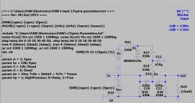
). Happy new year for all.For the amplifier I am testing something like this, what do you think of this?
Attachments
Good tutorial you found.
I think the voltage that develops over the electrolytic is the maximum voltage that the amp can deliver devided by the feedback factor that works like a voltage devider.
I do not know if there is any inrush peak.
Maybe Frans knows. 6V is low though.
I think 6V will do, but I would advice bipolar
(see also my previous post)What tutorial (is it a kind of easter-eg
For the amplifier I am testing something like this, what do you think of this?
So you use an extra V1 to create a polarizing voltage in the bipolar cap.... complex but very interesting.
So you use an extra V1 to create a polarizing voltage in the bipolar cap.... complex but very interesting.
Yes, this all due to the fact that I have my doubts about long term stability (and I want to use 500 to 1000uF coupling caps).
The polarizing voltage here is created from the 70V main supply. But it can be taken from any supply. Due to the nature of the application there is no current (other then the capacitors leakage) in the circuit, all resistors can be of high values. A filter R of a few 100K and C of a few 100uF can be used to power the polarizing source. This will be quite stable.
Also using very high R's will reduce any on/off plop's (has to be tested) (I think) (and there I am at the moment).
Thank you for your comments gentlemen.
I see Vbe changes will be minimal so output bias change will not be noticed.
Relating to the bipolar caps, do you believe those that are built as bipolar might not be so reliable as normal polar caps ?
I do not know
I tried to find long term reliability and stability information (specifically on the Nichicon site) and did not find any/much.The question is, how does the dielectric develop over time if the differential voltage is about zero volts (when used as a low signal input capacitor). And what is the difference between polar- and bipolar devices?
It seems to me that 'forced' polarization (as in the proposed schema earlier) will solve most 'unknowns' and that is what got me interested (To be continued
).No, i use bipolars all the time.
In power supplies they may have a disadvantage because they have more losses.
Whereas a good 1000uF low ESR elcap may have less then 10mOhm at 100kHz a comparable bipolar may have 100mOhm.
On the other hand a bipolar has less distortion so in the signal path it has an advantage over polar.
By the way a true bipolar has even less distortion then a " fake " back to back electrolytic.
See Bateman.
Here is the whole schebang :
Capacitor Sound
Very long and detailed but highly recommended. He turns all the stones.
Capacitor Sound
Very long and detailed but highly recommended. He turns all the stones.
- Status
- This old topic is closed. If you want to reopen this topic, contact a moderator using the "Report Post" button.
- Home
- Source & Line
- Analogue Source
- JG´s Nobrainer and Nobrainer Discrete