Magura, those sure are nice. I however l don't intend to
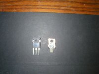
push mine hard only ~8 or 9 w or so. So I decided to salvage a couple of blown itfp240 mosfets and remove almost all the plastic.
Then sand the dead active device off exposing the copper base
and solder the jfet there. I hope the indium solder that melts
at ~97 c doesn't melt when I use the devices! I put a healthy
Irf260p in the picture besides my soldered Jfet.
Attachments
flg said:I haven't tried any soldering on these JFETs yet but on a daily basis I do such things with similar devices to heavy copper PCBs.
Please drop me an eamil, as I can't mail you.
Magura
")
woody said:Does anyone know the thermal resistance of that device from
case to heatsink?
Of the JFET itself, or the ones I made?
Magura
Magura said:
Of the JFET itself, or the ones I made?
Magura
ya have source of teflon tape , adequate for your "devices"
?
Zen Mod said:
ya have source of teflon tape , adequate for your "devices"
?
No, I use Kapton film
Magura
Thickness?Magura said:
No, I use Kapton film
Magura
Because I've only found 0.0015". Actually it was a while ago maybe it was 0.005"
 At 5000V/.001" dielectric strength, the thinner the better as long as you've checked for burrs and high spots etc.!
Why not use Kapton as the dielectric in your Quasi T-Clad developement project? It's high temp. It even comes with tape goo from Office Depot. Maybe you can get good high temp goo and make real High Performance thermal substrates. I'ld respond by e-mail but I've had to shift gears and think about all that T-Clad stuff in order to respond with a good answer...
While I'm thinkin 'bout it. I think you would have reasonable reliability (real good for the Magura/C/W normal levels) starting at 10W and possibly as high as 20W for that device. N.P. suggests 10W as a max? I would say 20W. N.P. also talks about the Vds vs Ids and load line linearity. That is where 2-3Vds is important. If your doin 10-20W at 3V thats 3.5-6+ Amps. This aint an F3 clone
But what could it be???

Magura said:
No, I use Kapton film
Magura
well - I meant on that ....... but seems that short circuit between headphones of mine was shorter than usual .......

same question ........ ?
Zen Mod said:
well - I meant on that ....... but seems that short circuit between headphones of mine was shorter than usual .......
same question ........ ?
Phase change material, RS stocks it, Bergquist makes it. Nice to work with, works very well.
Magura
DISCLAIMER: I gave an answer to what I believe the question is.
flg said:
Thickness?
Because I've only found 0.0015". Actually it was a while ago maybe it was 0.005"
Why not use Kapton as the dielectric in your Quasi T-Clad developement project? It's high temp. It even comes with tape goo from Office Depot. Maybe you can get good high temp goo and make real High Performance thermal substrates. I'ld respond by e-mail but I've had to shift gears and think about all that T-Clad stuff in order to respond with a good answer...
While I'm thinkin 'bout it. I think you would have reasonable reliability (real good for the Magura/C/W normal levels) starting at 10W and possibly as high as 20W for that device. N.P. suggests 10W as a max? I would say 20W. N.P. also talks about the Vds vs Ids and load line linearity. That is where 2-3Vds is important. If your doin 10-20W at 3V thats 3.5-6+ Amps. This aint an F3 clone
But what could it be???
I can't remember how thick the Kapton film I have is, I bought it long ago.
Yeah, I see you get the picture of where I'm heading
Kapton will though not be an option, as the thermal cycling will be a deal breaker.
Magura
Hey Magura, What about Mica between the primary copper heat spreader and the main heatsink? I may be wrong, but I seem to remember that mica is a better heat conductor and better electrical insulator than most of the synthetic insulator materials. Only thing that is an issue is that it's hard to get nice flat, planar pieces of mica.
Peace,
Dave
P.S. you could also go synthetic diamond, but that might move the cost up just a bit.
Peace,
Dave
P.S. you could also go synthetic diamond, but that might move the cost up just a bit.
udailey said:So what type of screw/bolt are you using? Nylon?
Uriah
Plain steel bolts. Isolation is sorted out by a shoulder washer.
Magura
Thickness?
McMaster has .002 thick "thermally conductive" Kapton. Has anyone tried this? I was considering getting a sheet for my next amp (if the design is ever published.....).
They have other thicknesses available in the "electrically conductive" variety, but I'm guessing this is not what you want.
JJ
- Status
- This old topic is closed. If you want to reopen this topic, contact a moderator using the "Report Post" button.
- Home
- Amplifiers
- Pass Labs
- JFET's ready for abuse