paulb said:What do the golden ears think?
How much gain are you getting from this? Maybe it would make a good headphone amp.
I'll be troubling the "golden ears" later today. I'm not going to tell her I changed anything, just in case she's biased.

I do notice that the detail is very present, and that I can turn the receiver up a great deal higher without distortion. The sound is still very sweet. I'm in love....

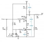
carpenter said:I made a few modifications to my first drawing and like the way this fellow sounds:
This circuit should not really work. Are you certain that it's
correct?
Nelson Pass said:This circuit should not really work. Are you certain that it's
correct?
I think the Voltage on the IRF930 Gate to source, to be 9.1V? In other words, on hard, it would be contributing to only mili ohms in the JFET biasing. So it is essentially not there and you have a JFET with a 27 ohm R in it's source. But I think it would work...

If Carpenter you have .103V at the source R then you must have 3.8mA in that R. And if you have 18V on the Rl then that is also about 3.8mA... Shouldn't it work?
Nelson Pass said:
This circuit should not really work. Are you certain that it's
correct?
It works and sounds good. Now I'm baffled!
I made a few more changes:
Attachments
I'm just dashing through, but it looks as though the IRF serves as a CCS to the JFET. That works if you're using a P-ch as a load, but to put a CCS under the tail of a device is a different matter entirely. The JFET's Source will bounce with the signal and very little, if anything, will come out of the Drain.
Or to put it another way, a CCS will deliver constant current, by definition. Given that the entire process of amplification depends on being able to vary the current seen by the amplification device's load, a constant current implies no signal--R4 will remain steady at 18V drop. The only signal you should hear would be the imperfections of the current source, which ain't gonna be a pretty sound at all.
Grey
it's all wrong ;
there is no single one DC point with plain logic ;
grey - how you think that triode with ccs in cathode and resistor in anode amplifies ............ ?
or I'm missing something , as usuallllllll ........ ?
naah ..... I see now - your comment is for this particular case ......
wakoo writer ....... ya can't be clearer sometimes .... ?

woodie - what's IRF930 ?
I can't find any useful data for that critter ;
take one 9V battery ; put + of battery to your gnd ;
unleash that poor .......................
blablabla
look at pic , just try it and say is it better .......
EDIT!!!!!!!!!!!!!!!
make that R6 at least 100-120 ohms
there is no single one DC point with plain logic ;
grey - how you think that triode with ccs in cathode and resistor in anode amplifies ............ ?
or I'm missing something , as usuallllllll ........ ?
naah ..... I see now - your comment is for this particular case ......
wakoo writer ....... ya can't be clearer sometimes .... ?
woodie - what's IRF930 ?
I can't find any useful data for that critter ;
take one 9V battery ; put + of battery to your gnd ;
unleash that poor .......................
blablabla
look at pic , just try it and say is it better .......
EDIT!!!!!!!!!!!!!!!
make that R6 at least 100-120 ohms
Attachments
GRollins said:I'm just dashing through, but it looks as though
the IRF serves as a CCS to the JFET. Grey
...except that it isn't much of a current source.
The MOSFET is acting much more like a low value
resistor with 8.9V across the gate and the source.
That may be related to your second point, that
the output reflects the imperfections of the current
source.
Jeremy
Thanks for the input, fellows. I've got a bit to learn.......
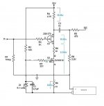
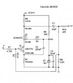
I quit the CCS process and found a better use for the ZVN3310 mosfet: I made a cascode arrangement.
I'm sticking with the 32 volt PS.
The jfet, once again, has the original 10ohm source resistor and its drain connects to the mosfet source just like ZV8. In fact, I followed the ZV8 process through out. The mosfet drain resistor value is 3.3k. I used a 9.1v zener in place of a pot to charge the gate of the mosfet.
I'll put up a picture later, right now I'm having quite a good time listening to my cascoded version of the jfetBOZ!
I've got a bit to learn.......I quit the CCS process and found a better use for the ZVN3310 mosfet: I made a cascode arrangement.
I'm sticking with the 32 volt PS.
The jfet, once again, has the original 10ohm source resistor and its drain connects to the mosfet source just like ZV8. In fact, I followed the ZV8 process through out. The mosfet drain resistor value is 3.3k. I used a 9.1v zener in place of a pot to charge the gate of the mosfet.
I'll put up a picture later, right now I'm having quite a good time listening to my cascoded version of the jfetBOZ!
Lemme see if I can summon a few brain cells...(sound of whistling...here boys...come on back now...).
Okay, R2 and Z1 define a DC reference for the MOSFET (parts numbers from the more recent schematic). If, at any point, you define a DC reference as input for a gain device it becomes a current source. Note that there's no connection at the node between the input, R1, and R3. (At least according to the schematic...what's actually happening is between consenting adults, and I will not inquire too closely.)
Low value resistor...yes, but no...
Grey
GRollins said:Lemme see if I can summon a few brain cells...(sound of whistling...here boys...come on back now...).
Okay, R2 and Z1 define a DC reference for the MOSFET (parts numbers from the more recent schematic). If, at any point, you define a DC reference as input for a gain device it becomes a current source. Note that there's no connection at the node between the input, R1, and R3. (At least according to the schematic...what's actually happening is between consenting adults, and I will not inquire too closely.)
Low value resistor...yes, but no...
Grey
Leave it to an amateur like myself to come up with something so weird!

BTW, should there be a connection at the node between input, R1, and R3? I thought that you might be giving me a hint...
Zen Mod said:
woodie - what's IRF930 ?
I can't find any useful data for that critter ;
take one 9V battery ; put + of battery to your gnd ;
unleash that poor .......................
make that R6 at least 100-120 ohms
I made a mistake with the mosfet number, its: IRF630B--sorry for the screw-up.
I didn't try the battery, but I did move R1 and R8 to the top of the zener. That placed them 9 volts higher than ground, right? Volume diminished, sounded smooth, don't know if I did anything beneficial. I gave up on the poor beast before changing R6 to 100 ohms.....

Anyway, thanks so much for bearing with my ignorance.
carpenter said:I'll put up a picture later, right now I'm having quite a good time listening to my cascoded version of the jfetBOZ!
Very good try with the cascode. Congratulations.
Could you tell us how the sound is different from Papa's simple one?

Babowana said:
Very good try with the cascode. Congratulations.
Could you tell us how the sound is different from Papa's simple one?
Thanks for plug, Babowana!
There's more gain, this allowed me to use negative feedback. This quieted the top-end sibilance. I'm deaf on the top-end, but the golden ears cringes--thus, the reason for feedback. I may add a switch to defeat the feedback loop. I like the sound of no feedback--I enjoy hearing the many delicate sounding ghosts in the attic.
The sound is quite similar, I wanted to cascode the jfet in order to increase the operating voltage. I'm currently in the safe region, at 32 volts, but soon, I wish to increase the voltage to 45 volts or so. I read that mosfets sound better with higher voltages.......
carpenter said:
................I read that mosfets sound better with higher voltages.......
and current - too ........
because you can't put more current through eeny jfet - it's better to use more adequate - little bjt for that, than starve IRF630 in that place
Zen Mod said:
and current - too ........
because you can't put more current through eeny jfet - it's better to use more adequate - little bjt for that, than starve IRF630 in that place
I'm using the ZVN3310 in the cascode arrangement, it shouldn't require as much current as the IRF630. What if I were to double up on the jfets? Also, would you use the bjt just like the mosfet as a cascode?
carpenter said:
I'm using the ZVN3310 in the cascode arrangement, it shouldn't require as much current as the IRF630. What if I were to double up on the jfets? Also, would you use the bjt just like the mosfet as a cascode?
sorry - I just forgot that zvn part ...... and I saw that ..........
it's good for that role ;
regarding bjt as cascode- again - look at

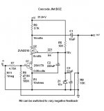
This is my conclusion to the ZV8 conversion. I personally enjoy the sound of the 100k feedback resistor, so I'm including a switch to satisfy both sets of ears in my family. Using a three way switch, I can totally eliminate the feedback, hence the 1meg resistance at the input.
I lowered the drain resistance in the mosfet in order to get the amperage to more closely correlated to that of the jfet source.
I lowered the drain resistance in the mosfet in order to get the amperage to more closely correlated to that of the jfet source.
Attachments
carpenter said:I personally enjoy the sound of the 100k feedback resistor, ...
I would try without the feedback, by removing R6.
For this, I would change R9 values to 1K and R8 to 2.2K
to adjust the voltage gain. The mod is easy, isn't it?
Babowana said:
I would try without the feedback, by removing R6.
For this, I would change R9 values to 1K and R8 to 2.2K
to adjust the voltage gain. The mod is easy, isn't it?
I'll give it a shot... the mosfet drain's 16 volt reading will probably alter. Edit: it did--26.6 volts. I thought the objective was to keep it centered between positive and ground.
If you have a moment, can you teach me more about the correlation between R8 and R9?
Also:
I find myself wondering what it would sound like if I were to replace R9 with a miniature, 1H choke.....there's very little amperage, the choke probably wouldn't saturate, the efficiency might increase. I find myself drawn in this direction--probably because I enjoy my ZV7-T so much.
- Status
- This old topic is closed. If you want to reopen this topic, contact a moderator using the "Report Post" button.
- Home
- Amplifiers
- Pass Labs
- JfetBOZ mods