Ok, now I feel dumb. In my desperation, I actually read the spec sheet and noticed that anything much over 0.2Vpp is going to distort... ........:
think in terms of effective Ugs
while G is going up, S is also going up
JFet is seeing just what's actually happening between G and S
if you nail S to fixed potential, only then you count biasing voltage as specific for maximum input swing
Ok, time to try again. Starting with the basic circuit that Nelson Pass provided in post #2 of this thread, and paying closer attention to the data sheet and my wiring, it's time for another day at the bench.
With the input voltage dialed down to 50mV, and using the test-mule Idss 7.3 device, the THD immediately dropped to 0.14%, and with tweaking, got it down as low as 0.12%, without feedback. I tried several different Id values (varying Rs and Rd), but Vds always ended up in the 3.5-4v range when tweaking for minimum distortion. Not what I expected - anyone have an idea?
---
Next task was to turn on the feedback to see if I can drive THD down. I have since figured out that I probably should have chosen a larger resistor for the feedback loop, as well as an even larger Rl, as both ended up maxed in several scenarios.
Initial turn-on of the feedback loop resulted in about a 24db gain loss, and THD was quickly tuned down to 0.0095 or so. I was trying to keep Vout at about 0.9Vpp (to match RCA-line-level voltage for the output), but this kept getting away from me. I probably would have managed slightly better THD numbers if I had kept an eye on the output voltage and gain...
Data for the run (harmonics are for H2, H3, H4 & H5) :
. harmonics -83/-88/-92/-97, THD 0.0095%
. gain 1.97/0.052, or 37.88x (31.5 dB)
. Id 0.45, Vds 4.6
. Rd 6.75k, Rl 5.35k, Rs 19.7, Rin 10 ohm, Rfb 23.3k
Remember that I have named the resistors Rd for Drain resistor, Rl for Load resistor, Rs for Source resistor, Rin for the input (gate) resistor and Rfb for the feedback resistor. Probably easy enough to figure out, but I thought I'd be careful with my nomenclature. Also note that Nelson's design does not have a feedback resistor in it. Mine goes from the outboard side of output cap (between cap and the 475 ohm output resistor) back to the gate.
---
I noticed that Vds was low in the earlier tests, so I cranked the voltage up to 40 volts, the THD went way up (to 0.025%) - so much for the sweet spot.
With some tweaking, I got the THD down to about 0.006x% with the x being in the lower digits. The output voltage is still a bit high, so I've probably given away some THD...
The data for this run:
. harmonics -90/-95/-90/-95, THD in the 0.006x% range (bouncing around in the lower digits)
. gain 1.12/0.035, or 32x (30.1dB)
. Id 4.5, Vds 4.3.
. Rd 7.91k, Rl 4.86k, Rs 19.7, Rin 10 ohm, Rfb 23.3k
Just for giggles, I plugged in some E24 resistor values and got the following results:
. harmonics are -82/-95/-90/-93, THD of 0.009x%
. gain 1.20/0.042, or 26.7x (28.5dB)
. Id 4.5, Vds 5.7
. Rd 7.50, Rl 4.71, Rs 20, Rg 10, Rfb 24.0
As "bad" as this THD looks (compared to the best numbers), I was able to get back into the high 0.006x range by simply running Rl up to max (about 10k), which also happens to be an E24 series value. So even with less "super" resistors I normally have in my parts bin, it looks like I can get quite nice results with stock resistors, I'll just need to try a few values out to make sure I've got the best numbers possible.
That wrapped up the work with RCA-level (-10dBv) output gains.
---
Time to try to see if I could boost an input signal to XLR/balanced voltages (about 3.5Vpp). This required boosting the input signal, as the feedback resistor was maxed out. I was able to keep the input voltage under 0.2Vpp, but not by much. Since the Id is on the low side, the signal will still swing into non-linear portion of the curve. I eventually got a series of results, each with THD at or just above 0.010%, with Id values ranging from 4.3 up to 7.0, and Vds from 6.3 to 7.3. The minimum THD followed a ratio between Id and Vds.
---
That maxed out the Idss 7.3 part, so it was time to switch in the Idss 6.5mA part. With the new part, I was able to tweak things so it did a little better and break into the double-oughts, 0.0095% THD! In the process the Id went down 0.7mA and Vds went up about 3.5v, but the output voltage remained the same. I turned the knobs again (including tweaking Rs) and got the THD down a little lower:
. harmonics are -87/-87/-95/-99, THD in the low 0.007x%,
. gain 3.48/0.163, or 21.35x (26.5 dB)
. Id 6.1, Vds 9.8
. Rd 4.98k, Rl 9.70k, Rs 1.1, Rg 1.44k, Rfb 45.3k
---
While researching XLR input values and XLR pre-amps, I noticed quite a few quoted their THD and THD+noise figures at 2Vpp output, so I cranked the input pot down until I was at nearly 2.0Vpp (1.98 - as close as I could get) and got the THD down to 0.0059%, w/ harmonics of -92/-93/-94/-96 - very nice!
---
With that done, I tried to lower the power supply voltage, but with the power supply reset from 40v to 35v, the lowest I could get the THD number was 0.015%, and 24v was worse, doing a best of just 0.025%.
What I drew from this is that lower Idss parts seem to respond a little better, and higher power rails helps as well. Sweet spots seem to cluster along a line of Rd (and Id) and Vds (and Rd). It might be time to retire the Idss 7.3 part and get serious with the good parts, and bump up the supply voltage a little higher...
---
Exposition is done, here's the questions, framed thusly:
I'm trying to build a pre-amp that can take an RCA or XLR level input and pass it to an XLR based amplifier, which is why I tried to generate the XLR-voltage output levels. Obviously, this isn't a finished design yet (XLR being balanced and all that). Given that the XLR is in the 'top tier' equipment category, I don't want to build something sub-par.
********************************************************************
How good are these THD and harmonic numbers?
Should I stop playing and finish the design of the pre-amp?
Should I do some more work on the circuit topography (ie this layout is maxed out and a high quality pre- should have better numbers)?
********************************************************************
---
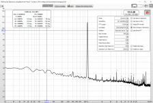
Odd note - I noticed my noise floor for my bread-board system was higher in the low frequencies and went down as frequencies went up. Any ideas? I presume it's all the point-to-point wiring, acting as antenna, but don't really know:
. noise floor at -100db above 1k, dropping to 110 by 10k, but -90 at 200hz, -80 by 20Hz
You can see this 'feature' in the first image below...
---
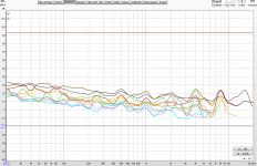
The first two images below are screen-caps from the test run using "standard resistors" from the E24 series (0.009% THD, tweaked with a different Rl to 0.006% THD) for a 40v power rail, the Idss 7.3 part and trying to keep Vout in the range for RCA devices. The 3rd is a re-post of original idea as presented by Nelson Pass in post #2 of this thread...
With the input voltage dialed down to 50mV, and using the test-mule Idss 7.3 device, the THD immediately dropped to 0.14%, and with tweaking, got it down as low as 0.12%, without feedback. I tried several different Id values (varying Rs and Rd), but Vds always ended up in the 3.5-4v range when tweaking for minimum distortion. Not what I expected - anyone have an idea?
---
Next task was to turn on the feedback to see if I can drive THD down. I have since figured out that I probably should have chosen a larger resistor for the feedback loop, as well as an even larger Rl, as both ended up maxed in several scenarios.
Initial turn-on of the feedback loop resulted in about a 24db gain loss, and THD was quickly tuned down to 0.0095 or so. I was trying to keep Vout at about 0.9Vpp (to match RCA-line-level voltage for the output), but this kept getting away from me. I probably would have managed slightly better THD numbers if I had kept an eye on the output voltage and gain...
Data for the run (harmonics are for H2, H3, H4 & H5) :
. harmonics -83/-88/-92/-97, THD 0.0095%
. gain 1.97/0.052, or 37.88x (31.5 dB)
. Id 0.45, Vds 4.6
. Rd 6.75k, Rl 5.35k, Rs 19.7, Rin 10 ohm, Rfb 23.3k
Remember that I have named the resistors Rd for Drain resistor, Rl for Load resistor, Rs for Source resistor, Rin for the input (gate) resistor and Rfb for the feedback resistor. Probably easy enough to figure out, but I thought I'd be careful with my nomenclature. Also note that Nelson's design does not have a feedback resistor in it. Mine goes from the outboard side of output cap (between cap and the 475 ohm output resistor) back to the gate.
---
I noticed that Vds was low in the earlier tests, so I cranked the voltage up to 40 volts, the THD went way up (to 0.025%) - so much for the sweet spot.
With some tweaking, I got the THD down to about 0.006x% with the x being in the lower digits. The output voltage is still a bit high, so I've probably given away some THD...
The data for this run:
. harmonics -90/-95/-90/-95, THD in the 0.006x% range (bouncing around in the lower digits)
. gain 1.12/0.035, or 32x (30.1dB)
. Id 4.5, Vds 4.3.
. Rd 7.91k, Rl 4.86k, Rs 19.7, Rin 10 ohm, Rfb 23.3k
Just for giggles, I plugged in some E24 resistor values and got the following results:
. harmonics are -82/-95/-90/-93, THD of 0.009x%
. gain 1.20/0.042, or 26.7x (28.5dB)
. Id 4.5, Vds 5.7
. Rd 7.50, Rl 4.71, Rs 20, Rg 10, Rfb 24.0
As "bad" as this THD looks (compared to the best numbers), I was able to get back into the high 0.006x range by simply running Rl up to max (about 10k), which also happens to be an E24 series value. So even with less "super" resistors I normally have in my parts bin, it looks like I can get quite nice results with stock resistors, I'll just need to try a few values out to make sure I've got the best numbers possible.
That wrapped up the work with RCA-level (-10dBv) output gains.
---
Time to try to see if I could boost an input signal to XLR/balanced voltages (about 3.5Vpp). This required boosting the input signal, as the feedback resistor was maxed out. I was able to keep the input voltage under 0.2Vpp, but not by much. Since the Id is on the low side, the signal will still swing into non-linear portion of the curve. I eventually got a series of results, each with THD at or just above 0.010%, with Id values ranging from 4.3 up to 7.0, and Vds from 6.3 to 7.3. The minimum THD followed a ratio between Id and Vds.
---
That maxed out the Idss 7.3 part, so it was time to switch in the Idss 6.5mA part. With the new part, I was able to tweak things so it did a little better and break into the double-oughts, 0.0095% THD! In the process the Id went down 0.7mA and Vds went up about 3.5v, but the output voltage remained the same. I turned the knobs again (including tweaking Rs) and got the THD down a little lower:
. harmonics are -87/-87/-95/-99, THD in the low 0.007x%,
. gain 3.48/0.163, or 21.35x (26.5 dB)
. Id 6.1, Vds 9.8
. Rd 4.98k, Rl 9.70k, Rs 1.1, Rg 1.44k, Rfb 45.3k
---
While researching XLR input values and XLR pre-amps, I noticed quite a few quoted their THD and THD+noise figures at 2Vpp output, so I cranked the input pot down until I was at nearly 2.0Vpp (1.98 - as close as I could get) and got the THD down to 0.0059%, w/ harmonics of -92/-93/-94/-96 - very nice!
---
With that done, I tried to lower the power supply voltage, but with the power supply reset from 40v to 35v, the lowest I could get the THD number was 0.015%, and 24v was worse, doing a best of just 0.025%.
What I drew from this is that lower Idss parts seem to respond a little better, and higher power rails helps as well. Sweet spots seem to cluster along a line of Rd (and Id) and Vds (and Rd). It might be time to retire the Idss 7.3 part and get serious with the good parts, and bump up the supply voltage a little higher...
---
Exposition is done, here's the questions, framed thusly:
I'm trying to build a pre-amp that can take an RCA or XLR level input and pass it to an XLR based amplifier, which is why I tried to generate the XLR-voltage output levels. Obviously, this isn't a finished design yet (XLR being balanced and all that). Given that the XLR is in the 'top tier' equipment category, I don't want to build something sub-par.
********************************************************************
How good are these THD and harmonic numbers?
Should I stop playing and finish the design of the pre-amp?
Should I do some more work on the circuit topography (ie this layout is maxed out and a high quality pre- should have better numbers)?
********************************************************************
---
Odd note - I noticed my noise floor for my bread-board system was higher in the low frequencies and went down as frequencies went up. Any ideas? I presume it's all the point-to-point wiring, acting as antenna, but don't really know:
. noise floor at -100db above 1k, dropping to 110 by 10k, but -90 at 200hz, -80 by 20Hz
You can see this 'feature' in the first image below...
---
The first two images below are screen-caps from the test run using "standard resistors" from the E24 series (0.009% THD, tweaked with a different Rl to 0.006% THD) for a 40v power rail, the Idss 7.3 part and trying to keep Vout in the range for RCA devices. The 3rd is a re-post of original idea as presented by Nelson Pass in post #2 of this thread...
Attachments
Last edited:
Hello everyone.... I'm new here.
This is a very interesting thread. I make JFET preamps for low impedance bass guitar pickups I make using a similar design that was derived from a preamp made by Alembic. The circuit is about 25 years old.
I'm curious to try this JFET BOZ design using 18 volts, from 2 9V batteries.
Here's the circuit I've been using, except I use a MPF-102 and the output cap is 4.7uF.
It's variable gain, and I usually use it all the way up.
")
How can i use 2SK170 JBOZ with varaiable Gain?
How can i use 2SK170 JBOZ with varaiable Gain?
Greetings:
In my tests, I was able to adjust the output voltage several ways.
1) reducing the input voltage with a pot before getting to the JFET (the 25k pot in the drawing)
2) reducing Rl on the output side can reduce the output voltage (the 2.2k attached to ground) *
3) introducing a feedback resistor (not shown on the diagram) from the output side of the capacitor back to the gate
I built a board with nearly every resistor replaced by a pot and played with it, just to see what would happen. You might want to do something similar, to see what gets you the results you are looking for.
* note that Rl also can impact the ratio of the second and third harmonics, depending on other settings, so achieving a balance between output voltage and harmonics is important (at least to me). 8)
Greetings:
In my tests, I was able to adjust the output voltage several ways.
1) reducing the input voltage with a pot before getting to the JFET (the 25k pot in the drawing)
2) reducing Rl on the output side can reduce the output voltage (the 2.2k attached to ground) *
3) introducing a feedback resistor (not shown on the diagram) from the output side of the capacitor back to the gate
I built a board with nearly every resistor replaced by a pot and played with it,
############ thats a good idea!
just to see what would happen. You might want to do something similar, to see what gets you the results you are looking for.
* note that Rl also can impact the ratio of the second and third harmonics, depending on other settings, so achieving a balance between output voltage and harmonics is important (at least to me). 8)
ok, thanks a lot.
is it possible to do something like in post #483
https://www.diyaudio.com/forums/pass-labs/103050-jfet-boz-49.html#post1365082
the reason is, i want to place a simple preamp before my Hiraga 30W amp.
with standard JBOZ there is too much gain and i can hear hissing noise.
i did something similar, with changing source and drain resistor in JBOZ for connecting to my Hiraga Le Monstre- and there it works fine.
But unfortunately not with my 30W Hiraga one...
Last edited:
That is for a guitar amp, which tends to have somewhat more lax requirements for fidelity than a pre-amp for audio-quality listening. You can try it, and see how it sounds. I didn't try to use the Rs (source resistor) as a volume knob, nor did I put a capacitor in the circuit there, so I'm not sure what it will sound like.ok, thanks a lot.
is it possible to do something like in post #483
https://www.diyaudio.com/forums/pass-labs/103050-jfet-boz-49.html#post1365082
I found the circuit, as printed in Post 2 of this thread, to be a great place to experiment from, not a final design. But then I was going for a specific gain (much less than the design circuit) and from a smaller power supply voltage.the reason is, i want to place a simple preamp before my Hiraga 30W amp.
with standard JBOZ there is too much gain and i can hear hissing noise.
Hiss like that (in my meager experience) in a high-gain stage is usually input noise or power supply noise. Are you using batteries, as post 483 was, or are you using a switching power supply? Linear power supplies tend to hum, rather than hiss. Note that all resistors have some noise associated with them. Different types have different noise characteristics. There's a reason audio projects tend to use metal film resistors, as they tend to have much lower noise than simple carbon resistors.
Amplifiers will amplify whatever they can find. Even if it is heat-noise from a crumby resistor. If you need less gain, the hiss will drop in proportion, if you can reduce the gain (a feedback resistor can do that, but it impacts the tone, usually for the better, but not always).
That wasn't a lot of help, but it might get you started on finding the hiss, and to better understand the circuit. Explore and play with the circuit. There are tons of JFET articles for amplification circuits, if you care to dig deeper.
I am not familiar with the amps you mention. It might be worth researching what the input characteristics are for them. Input impedance and sensitivity (input voltage needed to give a certain power output level) would be key to designing a pre-amp to match them.i did something similar, with changing source and drain resistor in JBOZ for connecting to my Hiraga Le Monstre- and there it works fine.
But unfortunately not with my 30W Hiraga one...
Greetings:
I built a board with nearly every resistor replaced by a pot and played with it, just to see what would happen. You might want to do something similar, to see what gets you the results you are looking for.
8)
Dear kking85743,
i need gain about 10db
which values for the trimmers/ pots instead of resistors would you recommend for starting the test?
Do you think, power supply of 9V would be a good option, too?
best
Dear kking85743,
i need gain about 10db
which values for the trimmers/ pots instead of resistors would you recommend for starting the test?
Do you think, power supply of 9V would be a good option, too?
best
I was looking for a specific voltage out, so I didn't really do any design/analysis in dB. I just calculated the results afterwards. How big is the input signal, as the output signal has to fit in the Vsd voltage range. Depending on the size of the output voltage, you may need to increase the power supply voltage to make sure Vsd is big enough. Hopefully that made sense.
I posted some notes a little ways back, that should give some ideas. The resistor values are directly related to the voltage, so that will be an important part of the experiment. I was using a bench-top variable power supply, so it was fairly easy for me to try different voltages. What voltage sources do you have available?
I found it was hard to do much with good fidelity even with 24v. 32v-40v for power was where the sweet spot was (but you need a big enough Rd (drain resistor) to keep from frying the jfet.
thanks,
i use battery supply, buffered by some electrolytics and am free in voltages
Possible are all voltages in steps of 1,5V
so i will try a higer voltage, than 24V
is 2k2 for drain resisotor too small for psu of 36V?
thanks,
i use battery supply, buffered by some electrolytics and am free in voltages
Possible are all voltages in steps of 1,5V
so i will try a higer voltage, than 24V
is 2k2 for drain resisotor too small for psu of 36V?
Sorry to be so long in replying, life got busy.
24v (for my purposes) was a little low, but it would be a great place to start. Nelson Pass did a great job with 19v (the Amp Camp Amp input stage), so that might also be sufficient for your purposes.
In my attempts, I found I was using between 7k and 10k for Rd, but that was at 40v, so you would have to scale it by about 1/2 for 20v and a little over half for 24v. That still leaves an Rd of 2.2k looking like it may be a little low. But I don't know. It will depend on your actual supply voltage, the Idss of the jfet, and what you are trying to do with the circuit.
I strongly suggest that you get a few potentiometers for the key resistors, and find out what works best for you. Then, once you have acceptable baseline values, measure the resistors you have (or look up resistors that you can buy). Then set each potentiometer to the nearest available value, and see what happens to the circuit. You may find (as I did) that by moving from the "perfect" value to an standard value, the values of other resistors may have to be changed.
A question for you - how are you deciding when the circuit is good enough? By simulation, by ear (listening to what it sounds like), or do you have some test equipment?
An externally hosted image should be here but it was not working when we last tested it.
j- Home
- Amplifiers
- Pass Labs
- Jfet BOZ