Thanks for the reply Mike,
I see what you mean on the pops, but I don't think we should be connecting cables with the amp or pre powered?
Yeah I see what you mean about the voltage on the drain - could change.
Now i can see why you would want it positioned as such in the BA3.
appreciate it!
I see what you mean on the pops, but I don't think we should be connecting cables with the amp or pre powered?
Yeah I see what you mean about the voltage on the drain - could change.
Now i can see why you would want it positioned as such in the BA3.
appreciate it!
Attachments
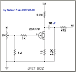
on jboz you can remove complity the 2.2k and 475r just use care ie power off if you play at cable")
and thank you as well for looking into my question
I'm terrible at understanding these (even simple) topologies. Little things help! If I had more time to play I think it would be different.
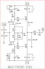
Zener diodes replaced by TL431
Is someone can help me in order to replace the diodes as has done ramallo
Schematic with Value for The R and the potentiometer and how to connect it to the PCB
Regards
Philippe
Is someone can help me in order to replace the diodes as has done ramallo
Schematic with Value for The R and the potentiometer and how to connect it to the PCB
Regards
Philippe
No, nothing on D6
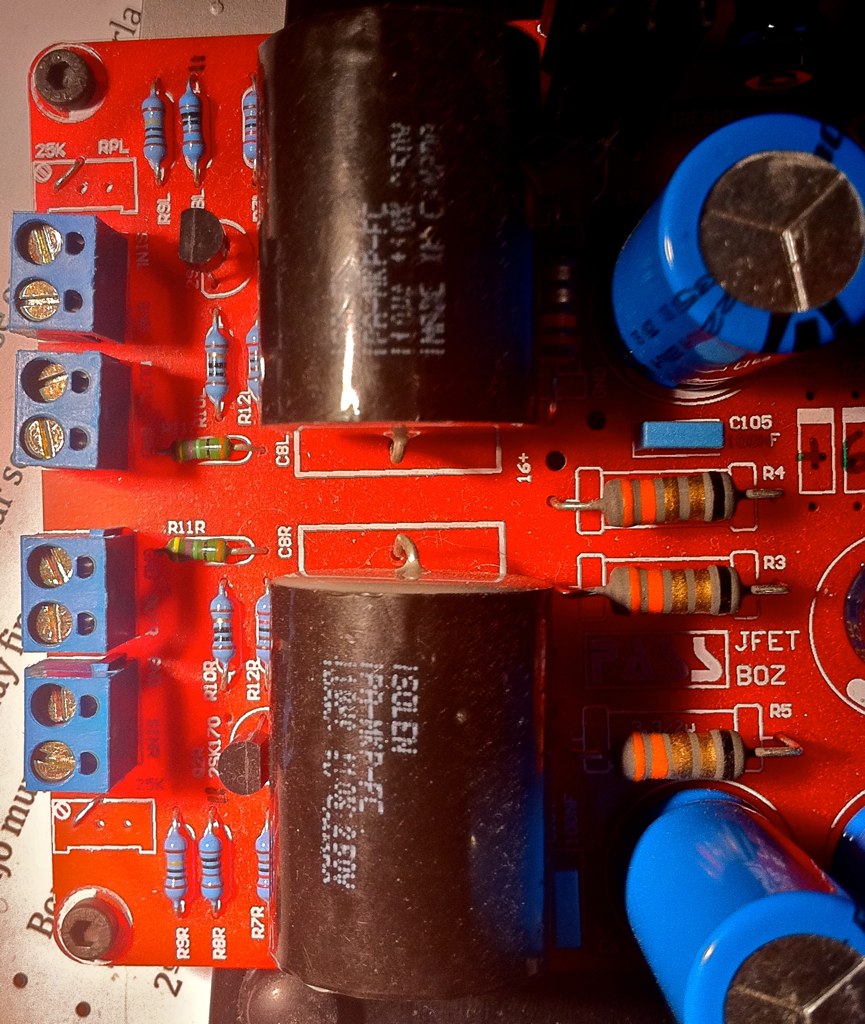
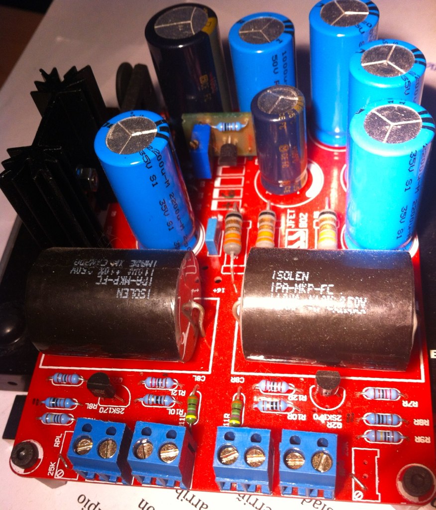
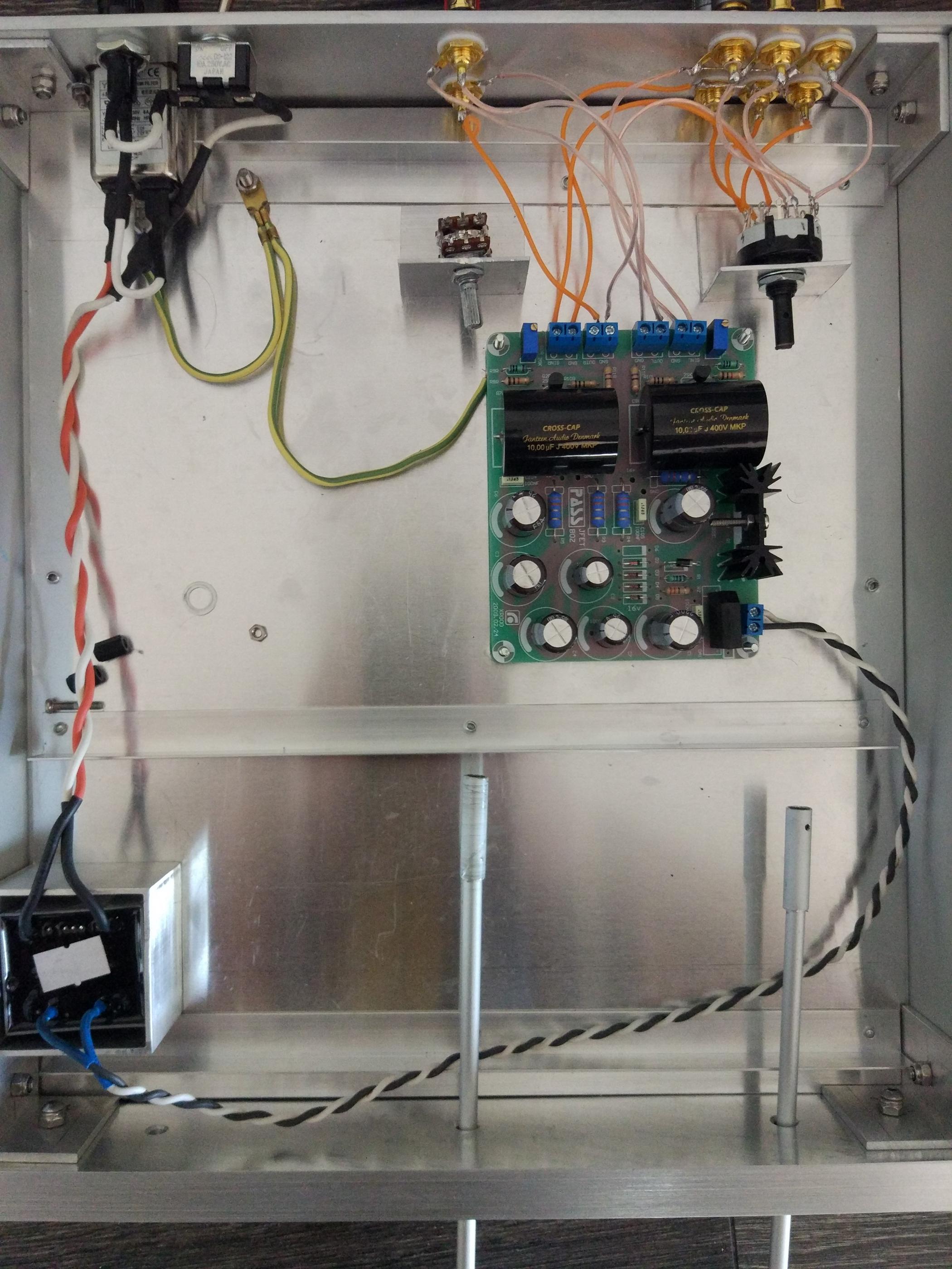
In this photos I have replaced the diodes by a TL431 circuit (For fine tuning the V supply)

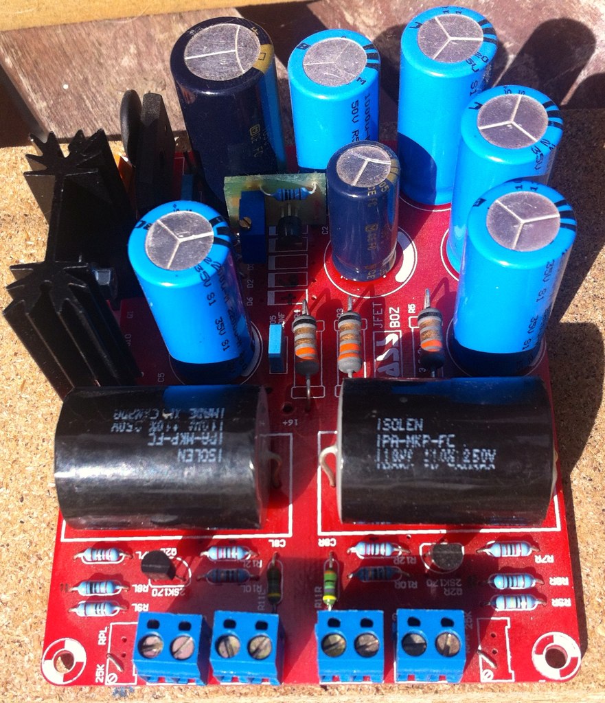
I actually started on this project to make an integrated amp with a jfet-boz driving a Zen-v9 several years ago, but life intervened. I am coming back to it now and working my way through this entire thread! I have a pcb that I made up with two jfet-boz and a zener/IRF640 voltage regulator. Since the Zen-v9 wants 50VDC and I happen to have an infinite source of 50VDC in my house batteries, I am wondering if with so little current draw from this circuit, the zener/IRF640 can handle a 30V drop (50->16 with 4V for 640)? I'd appreciate input from someone more knowledgeable before I plug it in and blow it up. I know the parts are not expensive, but GETTING them here in Panama is a problem.Using the zener diodes and the IRF610 I get EXACTLY 14V - and it is DEAD SILENT.
Thanks
Here's another alternative: 24 x 2V/800ah lead acid batteries charge by the sun, no AC ever! and you can listen 24/7! Of course it also runs my entire house via an inverter, but I can tap into them before the inverter for really clean and limitless DC.You can always use 2x12v 7ah lead-acid batteries in series. Build a trickle charger to keep them full. Relay connects the charger when preamp is not in use (overnight). The only caveat is if you listen to it 24h/day..
Nice alternative, isn't it?
Back to Nelson's little circuit. Supose I wanted to run 2 2sk170's in parallel, use 10 ohm source resistors on each 2sk170 and change the drain resistor to 1.1k . How close would I need the 2sk170's matched ? Would a pair of devices with an IDSS of 9.0 ma and 10.5 be considered a close enough match.
Attachments
and the alternative question should be:Back to Nelson's little circuit. Supose I wanted to run 2 2sk170's in parallel, use 10 ohm source resistors on each 2sk170 and change the drain resistor to 1.1k . How close would I need the 2sk170's matched ? Would a pair of devices with an IDSS of 9.0 ma and 10.5 be considered a close enough match.
If I run the two slightly different jFETs in parallel, without source resistors, will the circuit perform well? You still need the 10r from the commoned sources to set the gain of the amplifier.
I don't know the answers.
Build four versions, matched and unmatched jFETs with 10r source resistors to each and matched and unmatched jFETs with zero ohms substituted as the source resistors.
Measure and listen and see if there is a difference/preference between the 4 options.
Last edited:
....have a look at " the pearl phono stage ",
paralleled input fet seem to be unmatched.
Actually the Pearl input stage Jfet are matched, although the source resistors help balance things somewhat.
I think Nelson said that the optimum Vsupply depended on the individual JEFT.. His might have been +16Volt.. I'll attach a plot so you can more or less see what you optimum Vsupply is when you know your Idss.... as a bonus the THD is predicted too....
Red = THD in %
Blue = Voltage supply/10 in Volts
In order to optimize the supply voltage to my simple JFET RIAA, I have found this survay of optimized voltage for different IDSS values (post #579+580 here).
But looking into the values, they look suspect to me:
-The case with the IDSS of 16mA and 28.9V supply, would result in ID=12.5mA and VDS of 1.4V...
-The case with IDSS of 8mA and 16.3V supply, would result in ID=8mA and VDS of 3.1V...
Are there anyone else having input on these results?
Last edited:
Maybe a 50K resistor in parallel with the 50K pot.
The curve will not be linear, but I tried before on an amp and worked fine.
The curve will not be linear, but I tried before on an amp and worked fine.
hello
J have almost finished the Boz and want to replace 25 input trimer by a pot
25K is not a standard value, my shop offers only 10K, 50K, and 100K.
What would be the best value ? Is it possible to modify a 50K pot to 25K pot ?
Regards
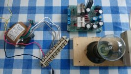
Hi, one newbie question, I'm trying to troubleshoot BOZ preamp that I've built for my ACA amp.
The board is from Jim's audio, I'm using 18V-0,39A transformer and getting about 26V at the BOZ input, using 4 4V zeners. The source is Hifiberry. There is 5k stereo pot at the output.
The case is that I'm getting really terrible distorsion at any volume level.
Where to start, what to check?
The board is from Jim's audio, I'm using 18V-0,39A transformer and getting about 26V at the BOZ input, using 4 4V zeners. The source is Hifiberry. There is 5k stereo pot at the output.
The case is that I'm getting really terrible distorsion at any volume level.
Where to start, what to check?
An externally hosted image should be here but it was not working when we last tested it.
Hi, one newbie question, I'm trying to troubleshoot BOZ preamp that I've built for my ACA amp.
The board is from Jim's audio, I'm using 18V-0,39A transformer and getting about 26V at the BOZ input, using 4 4V zeners. The source is Hifiberry. There is 5k stereo pot at the output.
The case is that I'm getting really terrible distorsion at any volume level.
Where to start, what to check?
Photos attached below:

Attachments

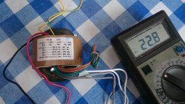
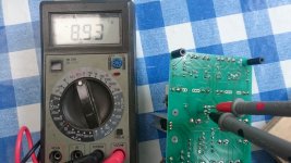
I have ensembled a Jfet boz. My trafo measures a bit higher than 18v but I guess it is ok unloaded. On the board it has measurement points which say 16+ and gnd. It measured 8,92v. Is this a problem and how can I correct it to get it to 16v?
Not tested running audio yet.
Not tested running audio yet.
Attachments
- Home
- Amplifiers
- Pass Labs
- Jfet BOZ