thanks to all!
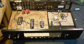
This has been an excellent thread and got me through (along with the regular BOZ threads and data) a couple of builds of the posted NP schematic. The only thing I had to tinker with is the resistor from the V+, 2.2K was not perfect but pretty darn close! (you may notice the 2.2K pot with big black knob in the lower center of the wood cased JBOZ; it's the best for tuning your input resistor") )
)
The second one is playing now downstairs, it is very involving. I'm grinning a lot listening to it every chance I get even while I know the sound will improve as things settle down inside their skins.
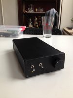
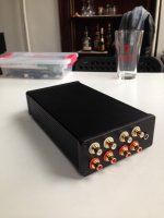
So for the newbies out there here is photographic evidence that cobbling Can work and persistence (with some kind help) will get you there.
The one in the wooden enclosure is the second build using a Lighter Note LDR instead of the 25K pot and some nice Russian PIOs instead of polyester - highly recommended.
This has been an excellent thread and got me through (along with the regular BOZ threads and data) a couple of builds of the posted NP schematic. The only thing I had to tinker with is the resistor from the V+, 2.2K was not perfect but pretty darn close! (you may notice the 2.2K pot with big black knob in the lower center of the wood cased JBOZ; it's the best for tuning your input resistor
)The second one is playing now downstairs, it is very involving. I'm grinning a lot listening to it every chance I get even while I know the sound will improve as things settle down inside their skins.
So for the newbies out there here is photographic evidence that cobbling Can work and persistence (with some kind help) will get you there.
The one in the wooden enclosure is the second build using a Lighter Note LDR instead of the 25K pot and some nice Russian PIOs instead of polyester - highly recommended.
Attachments
It is not exactly like a pot in that the Lighter Note is set up as a shunt resistor. The true function of this is a bit beyond me but it seems like with a shunt there is a more consistent impedance presented to the source. But hey, I am SO far from EE status
Maybe someone can chime in with real information...
Maybe someone can chime in with real information...
Hi all,
First time post here. It's been a great pleasure reading the contributions to this forum, as well as Nelson Pass's articles on audio, and a quick note of thanks is due.
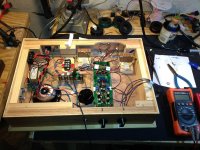
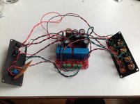
I recently built a JFET Bride of Zen using the kit from Jim's Audio/manu. I made a couple of modifications (larger filter caps, at 4700 uF, and an additional 4.1V Zener to get the PS up to ~15.9 volts) and did a bit of testing to ensure that I was operating at the board's sweet spot. With my matched 2SK170s (8.05 mA IDSS), varying the drain resistance gave the lowest THD at ~2.13 kOhms, so I went ahead and used the 2.2K's specified. This is in line with other data suggesting that 16V is optimal for the original circuit at IDSS = 8 mA.
I also changed the volume control section: rather than a 25k pot, I used a 200K pot followed by a 20Kohm voltage divider that throws away ~75% of the signal. I did this for the sake of full volume control---I know it's not kosher by Nelson's standards, but both my sources put out enough juice that the JFET BOZ will begin to distort very quickly with a 20K pot.
My setup is humble (Schiit Modi --> Topping TP20 --> Cambridge S30) but provides a remarkably deep, wide, and involving sound that tends slightly toward brightness. The sound is still pretty good with my new JFET BOZ into the signal chain, but with increased brightness and a rather narrower and shallower soundstage. Altogether, it sounds more congested and spatially "flat" than going direct from DAC to amp.
I'm posting to ask for some advice about the sound from this guy before I start making changes. I don't mind the brightness, but might anyone have any suggestions for recovering some of the depth from the original signal? Could my volume control section be at fault? Could the JFET BOZ simply be a mismatch for my system?
My first (uninspired) thought was to try a better pair of output caps. I'm currently using EPCOS B32676 (B32676E3106K EPCOS | Mouser). Interestingly, this same series was noted to have a "rather flat, 2D image" when unscientifically tested in speakers (Humble Homemade Hifi) -- and while this is the exact problem that I am having, I wouldn't be surprised if this is coincidence. Any chance that better caps might help?
First time post here. It's been a great pleasure reading the contributions to this forum, as well as Nelson Pass's articles on audio, and a quick note of thanks is due.
I recently built a JFET Bride of Zen using the kit from Jim's Audio/manu. I made a couple of modifications (larger filter caps, at 4700 uF, and an additional 4.1V Zener to get the PS up to ~15.9 volts) and did a bit of testing to ensure that I was operating at the board's sweet spot. With my matched 2SK170s (8.05 mA IDSS), varying the drain resistance gave the lowest THD at ~2.13 kOhms, so I went ahead and used the 2.2K's specified. This is in line with other data suggesting that 16V is optimal for the original circuit at IDSS = 8 mA.
I also changed the volume control section: rather than a 25k pot, I used a 200K pot followed by a 20Kohm voltage divider that throws away ~75% of the signal. I did this for the sake of full volume control---I know it's not kosher by Nelson's standards, but both my sources put out enough juice that the JFET BOZ will begin to distort very quickly with a 20K pot.
My setup is humble (Schiit Modi --> Topping TP20 --> Cambridge S30) but provides a remarkably deep, wide, and involving sound that tends slightly toward brightness. The sound is still pretty good with my new JFET BOZ into the signal chain, but with increased brightness and a rather narrower and shallower soundstage. Altogether, it sounds more congested and spatially "flat" than going direct from DAC to amp.
I'm posting to ask for some advice about the sound from this guy before I start making changes. I don't mind the brightness, but might anyone have any suggestions for recovering some of the depth from the original signal? Could my volume control section be at fault? Could the JFET BOZ simply be a mismatch for my system?
My first (uninspired) thought was to try a better pair of output caps. I'm currently using EPCOS B32676 (B32676E3106K EPCOS | Mouser). Interestingly, this same series was noted to have a "rather flat, 2D image" when unscientifically tested in speakers (Humble Homemade Hifi) -- and while this is the exact problem that I am having, I wouldn't be surprised if this is coincidence. Any chance that better caps might help?
Attachments
I doubt it's the caps. And I wouldn't call the Jboz bright. I wouldn't call a 2020 T-amp bright either. So something is going on. If anything better caps will make it brighter.
It could be the d/s resistor values in the boz...I had to play around with mine running on 16V of batteries. I ended up w/5 ohm source and 1K drain. I think the jfets were 8.5ma.
But probably, you have too much gain going on. Since the T-amp can be run sans preamp it has quite a bit of gain built in. I'd look at lowering the gain in the topping by changing some resistors. If you want to do a quick test try a pot between your dac and the jfet boz. This should lower the signal and allow to see if you have too much gain.
Read this:
http://www.e-ele.net/DataSheet/TA2020.pdf
I'd also bypass the volume ocntrol on the topping, I assume you have it wide open now. A few jumpers on the pot will do.
I'd go back to the 20K pot on the Jfet boz.
The tripath amps don't don't like being overdriven, things get nasty quick. Even if you can't hear it as distortion they will flatten out and misbehave when pushed hard. How loud are you listening? The wattage ratings on the T amps are kind of optimistic...you may be pushing the limits of the 2020 amp...I used a TK2050 amp (50W/100W) for years with a buffer in front of it. It was nice but didn't like to play loud. And it has more power than the 2020 chip.
Also, if you get the jboz figured out I'd experiment with input caps on the tripath. They influence the sound a lot.
Hikari---Thanks much for your thoughts. I hadn't considered the Topping because I volume-matched the input signals from the Modi DAC and boz before A/B'ing, and that level sounded fine coming from the Modi. I've observed this at mostly low-medium volume levels that I'm accustomed to in my apartment. The volume knob on the amp is anywhere between 11 and 2 o'clock for most listening (including these tests), as I also control volume directly from the computer source.
Is there any reason that the Topping would start to distort more rapidly with the boz than the Modi, even when they are outputting the same signal volume?
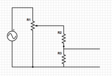
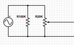
I will try switching the input pots back to 25k as well. Out of curiosity, is there any clear reason the setup I described above, with the voltage divider following a 20k pot, wouldn't work? I did some calculations in Excel to make sure that the resistances would play well together, but I also think that the input impedance might not be constant. (I am still reading up on this...) I've attached a schematic of the input circuit in case my words aren't clear (currently R1 = 200k, R2 = 15k, R3 = 4.75k).
Finally: The sound seems to relax and open up a bit when the signal goes through a source selector with an "impedance matching circuit" (TCC TC-716 Details and Hookup) between the boz/DAC and the Topping. I'm not sure what "impedance matching" indicates here. Either way, through the selector, the difference between the DAC alone and the boz almost disappears.
Is there any reason that the Topping would start to distort more rapidly with the boz than the Modi, even when they are outputting the same signal volume?
I will try switching the input pots back to 25k as well. Out of curiosity, is there any clear reason the setup I described above, with the voltage divider following a 20k pot, wouldn't work? I did some calculations in Excel to make sure that the resistances would play well together, but I also think that the input impedance might not be constant. (I am still reading up on this...) I've attached a schematic of the input circuit in case my words aren't clear (currently R1 = 200k, R2 = 15k, R3 = 4.75k).
Finally: The sound seems to relax and open up a bit when the signal goes through a source selector with an "impedance matching circuit" (TCC TC-716 Details and Hookup) between the boz/DAC and the Topping. I'm not sure what "impedance matching" indicates here. Either way, through the selector, the difference between the DAC alone and the boz almost disappears.
Attachments
that double attenuator arrangement should not be necessary.
Go back to the 20k vol pot.
Now tell us what this means.
Go back to the 20k vol pot.
Now tell us what this means.
I did this for the sake of full volume control---I know it's not kosher by Nelson's standards, but both my sources put out enough juice that the JFET BOZ will begin to distort very quickly with a 20K pot.
Muzzmastah,
When I switched my output caps to PIO things got very much better. I had been running polyester 10uF as NP had mentioned that type. For me PIO saved my smile.
I also would like to ditch some of the JFET BOZ's high sensitivity to input. It starts distortion lickity split with a touch of the volume pot (25K). I'm looking for the "best" way to tame this "characteristic" too...
that double attenuator arrangement should not be necessary.
Go back to the 20k vol pot.
Now tell us what this means.
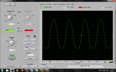
Andrew, thanks for the advice---I went ahead and tried this this morning. I've attached a screenshot of waveform produced from a 1khz sine wave with the volume knob at 10 o'clock. As you can see, there is some (not-so) nice asymmetrical clipping going on. I've read a bit about this occuring in the mosfet BOZ --- does this suggest I should change the drain/source resistors that are biasing the JFET?
My impression was that there is only so much linear territory on the Ids vs. Vgs curve for the transistor, and that the large voltage swings from a high-output source like this DAC (1.5V max, I'm assuming that means P2P) would thus need to be attenuated before they hit the 2SK170.
Test setup:
Audacity (Windows 7) --> Schiit Modi --> boz --> diy CMoy headphone amp --> line-in (built-in on Macbook Pro) --> Soundcard Scope software
I've measured THD from both the line-in and the headphone amp, and both measure 0.01% in the FFT function of the scope software, which is the bottom of the software's measurement range. The clipping waveform shown above remains when I attenuate the boz's output with the pot on the headphone amp's input, so it is not being caused by the headphone amp or the soundcard being overloaded.
JDG---appreciate the advice as well. Perhaps a cap replacement will follow once we get this distortion behavior sorted out.
Attachments
isn't it better to use buffer , instead of gain stage , in that setup ?
In this case, yep---but I was eventually planning on building a "real" amplifier (maybe F5) and thought I'd go ahead and make something with gain in case I need the extra juice later. Mark Houston has had very good things to say of his builds of the Jboz sans input caps vs. the B1 (Mongrel Dog Audio: Pass capless BoZSE), so I decided to give it a try
Edit: FWIW, the boz appears to sound significantly better with the 20K pot, low-level signal from the DAC, and the Topping input pot wide open...
Last edited:
removeable shunt?
I had a device made by the late George Wright that is just an RCA female joined to an RCA male; starts at the female center(+) with 90K resistor leading to a 10K from + to - (at the RCA male). One puts this at the input to the preamp, effectively becoming a 100K shunt? GW called them a "10x reducer". This knocks down the input for my JBOZ into the realm of very sweet, no distortion at all, but it takes too much out so that I don't have quite enough gain (for me) seems like just above unity.
This kind of thing might work for muzzmastah though and is completely removable for his future need of gain...
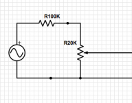
I was thinking about trying something like this earlier today to see what happens. To clarify, would it look like the schematic I've attached here?
Attachments
Re:my previous post (cannot edit): that should be a voltage divider with 90k in series on the positive rail followed by a 10k resistor to ground, which is rather like a reverse of my original arrangement. I suppose this is better because it presents the source with a constant input impedance?
Hi all,
First time post here. It's been a great pleasure reading the contributions to this forum, as well as Nelson Pass's articles on audio, and a quick note of thanks is due.
I recently built a JFET Bride of Zen using the kit from Jim's Audio/manu. I made a couple of modifications (larger filter caps, at 4700 uF, and an additional 4.1V Zener to get the PS up to ~15.9 volts) and did a bit of testing to ensure that I was operating at the board's sweet spot. With my matched 2SK170s (8.05 mA IDSS), varying the drain resistance gave the lowest THD at ~2.13 kOhms, so I went ahead and used the 2.2K's specified. This is in line with other data suggesting that 16V is optimal for the original circuit at IDSS = 8 mA.
I also changed the volume control section: rather than a 25k pot, I used a 200K pot followed by a 20Kohm voltage divider that throws away ~75% of the signal. I did this for the sake of full volume control---I know it's not kosher by Nelson's standards, but both my sources put out enough juice that the JFET BOZ will begin to distort very quickly with a 20K pot.
My setup is humble (Schiit Modi --> Topping TP20 --> Cambridge S30) but provides a remarkably deep, wide, and involving sound that tends slightly toward brightness. The sound is still pretty good with my new JFET BOZ into the signal chain, but with increased brightness and a rather narrower and shallower soundstage. Altogether, it sounds more congested and spatially "flat" than going direct from DAC to amp.
I'm posting to ask for some advice about the sound from this guy before I start making changes. I don't mind the brightness, but might anyone have any suggestions for recovering some of the depth from the original signal? Could my volume control section be at fault? Could the JFET BOZ simply be a mismatch for my system?
My first (uninspired) thought was to try a better pair of output caps. I'm currently using EPCOS B32676 (B32676E3106K EPCOS | Mouser). Interestingly, this same series was noted to have a "rather flat, 2D image" when unscientifically tested in speakers (Humble Homemade Hifi) -- and while this is the exact problem that I am having, I wouldn't be surprised if this is coincidence. Any chance that better caps might help?
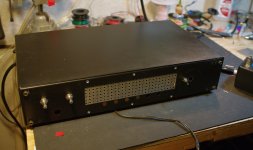
I use the same Hammond enclosures.
I use the same Hammond enclosures.
Indeed---I read your Jboz build pages more than a few times before starting my own, so I had that same thought often! I settled on this enclosure after a lot of shopping around. It's convenient, the plates are easy to drill, and it's < $30 from Mouser. At any rate, thanks for everything you've made available about your builds. It's been very helpful and encouraging.
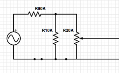
I've done some reading on an excellent page I found tonight (Volume control), and from what I can tell, I should be to put a 100k resistor in series before the volume control (see first attached schematic) in order to attenuate the input signal by 15-16 dB. I'm inclined to like this more than the 90k/10k voltage divider (see second attached schematic) simply because it uses one less resistor. Yet more questions: is there any clear reason why one should be better than the other? Or why either should sound better than the first arrangement?
I've continued my listening of my Jboz with the 20k pot and very low DAC output, with really great results. The soundstage and richness I was accustomed to are back, and the sound is really well-balanced---perhaps a bit less bright, and more pleasant, than the straight output from the DAC. Ideally there is a way to preserve this while attenuating the input at the Jboz, so I (1) can have decent volume control for my tuner, which does not have an output level control, and (2) don't have to take special measures to keep DAC output low.
Attachments
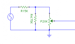
Tried a couple of attenuator arrangements today. The single 100K resistor in series (first schematic above) was effective and sounded better than the original, but not as good as the 20K pot alone. Next I tried the arrangement in the attached schematic---brilliant! It might all be psychoacoustics, but to my ear this was a clear winner. It also keeps the input impedance near the ~20K of the original circuit. Thanks all for the helpful input!
I've noticed that the sound has gotten progressively better with lower input impedances. Is there a reason I should have expected this?
JDG, I'd highly recommend trying this arrangement if you're looking for a less sensitive volume control.
I've noticed that the sound has gotten progressively better with lower input impedances. Is there a reason I should have expected this?
JDG, I'd highly recommend trying this arrangement if you're looking for a less sensitive volume control.
Attachments
- Home
- Amplifiers
- Pass Labs
- Jfet BOZ