Thanks for all your help. I must say, it is sounding pretty fine. Even my wife has commented on it more than once.
That cap (C15 in your diagram) is in the preamp box and it is currently the p.i.o. I mentioned. The power supply is in a separate box. Does the cap need to be right next to the Darlington? Maybe I should try another one (or pair) there - 2uF polyprop // .022 polyprop perhaps?
You say put the snubber // to C15? For snubbing, I usually use 150nF and 100 ohm. Are these good values in this case?
The 47uF (C13) is a used Black Gate, but the top is bulging slightly. I think I will replace it with a Pana FC and see if that solves the problem.
I have made the reg to give around 17v, so the resistor values in the pre-reg differ quite a lot from yours. In fact, they are much closer to the app notes from National Semi. I drew up a board for the cct in Coreldraw, pinted it out on label paper, stuck it onto a piece of pcb, drilled the holes, removed the paper, connected the tracks with marking pen and etched the board. It is possible I made a mistake somewhere. I have been known to do that (with monotonous regularity.)
Photos? Never done it - don't know how to do it. Perhaps I should ask my kids for some help in that department.
Tried all sorts of things. First, I substituted the BC548c with my favourite Zetex transistor (ZTX1054a). Got rid of most of the the annoying sound I was complaining about.
Noticed the Darlington was getting hot, so i fitted a real mother of a Darlington (BDV65C). Sound changed for the better some more, but still had stability problems. I replaced the 24v tranny with a 30v tranny to allow more headroom (I thought maybe the lm317's were dropping out of regulation or possibly there wasn't enough voltage across the CCS). I lowered the voltage drop of both 317's to make sure there was enough left for the CCS. At first, it seemed eminently stable at various voltages and shorted out one LED to make sure of the same thing from the other side if you know what I mean. The voltage into the IRF510 was rock solid, but as soon as I connected it to the preamp, it began to waver again, by about half a volt. Once this starts, it affects the whole power supply right back to the bridge. I think the darlington is oscillating because it got quite hot at one point, in spite of its huge over-specification for the job it is doing.
One thing is bothering me. The 30v, 2amp tranny is only able to supply just over 25v into the regulator, which seems to indicate that there is a heck of a current being drawn somewhere. What controls the amount of current the darlington dumps to ground?
hihopes said:Tr.....
One thing is bothering me. The 30v, 2amp tranny is only able to supply just over 25v into the regulator, which seems to indicate that there is a heck of a current being drawn somewhere. What controls the amount of current the darlington dumps to ground?
R8/R9
look here :http://www.diyaudio.com/forums/showthread.php?postid=1588700#post1588700
also look here :http://www.diyaudio.com/forums/showthread.php?postid=1627519#post1627519
even if I didn't check that xls file ;
can you post a pic?
Hi there. Thanks for your prompt reply. After looking through your description, I am wondering whether perhaps I have a problem with too much dissipation in R3, where I am using a trimpot. I originally had it paralleled with a resistor, but in all my fiddling, I removed the resistor.
I will look at the spreadsheet and see what I can learn from it.
Will it help if I can post a pic of my board layout I did in Coreldraw before making it? (It includes the pre-reg and CCS. The shunt element is on stripboard.)
I will look at the spreadsheet and see what I can learn from it.
Will it help if I can post a pic of my board layout I did in Coreldraw before making it? (It includes the pre-reg and CCS. The shunt element is on stripboard.)
hihopes said:Hi there. Thanks for your prompt reply. After looking through your description, I am wondering whether perhaps I have a problem with too much dissipation in R3, where I am using a trimpot. I originally had it paralleled with a resistor, but in all my fiddling, I removed the resistor.
I will look at the spreadsheet and see what I can learn from it.
Will it help if I can post a pic of my board layout I did in Coreldraw before making it? (It includes the pre-reg and CCS. The shunt element is on stripboard.)
most critical part of any PSU design is exact physical layout ;
look here , at atached scrible
 : http://www.diyaudio.com/forums/showthread.php?postid=1625171#post1625171
and - looking at upper half , you'll recognize Shiny ;
look how ground lines are drawn .
conclusion ?
btw. - I'm not good in starring at pcbs ... especially now , with the flue .
maybe someone else can comment , if you post a pic ;
just export it from Corel to any other graph format , then attach here
if you can't do that , send me a cdr file to >choky@neobee.net< , and I'll do that for you
hihopes said:For R8/R9, I originally had a 6,8r 2w resistor. I have now replaced it with a 10r 2w in the hope that lowering the dissipation might help the stability.
I tried a number of different values R and C in snubber configuration, but no improvement there.
snubber is cream on cake , not cure ;
Sorry to hear you have the flu. Hope you feel better soon.
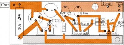
I'm afraid my psu looks nothing like that. It is all modular. Trafo; Board for bridge (Schottky diodes// Russian paper caps) + snubber; crcrc filter section - 330uF - 10ohm - 330uf-10ohm-10000uf//680uf Pana//.22uF polyrop; board for prereg and CCS; another board for diodes and darlington. Each section star-earthed to chassis ground. You think the grounding scheme may be where the problem lies?
BTW, there were some times that I had it stable, but noticed that when I connected the output wires, it started to fluctuate. Wires are about 1.2m long old computer power cable.
I will see what I can do with the cdr file, although that is only the prereg and CCS board.
I am thinking of testing a different kind of reg to see if there is maybe a problem with my slightly unusual bridge design.
Strangely enough, in spite of the instability, it sounds pretty good. I can't wait to hear what it sounds like once it is sorted out.

JBOZ as CD analog out
Hello,
I would like to replace the NE5534, single op-amp in the analog out of my CD player, with the appropriate version of the JFET BOZ. However, the BOZ output may be too high for my original BOZ driving a DIY (Andrea Ciuffoli's 2005 Power Follower) SE MOSfet amp.
I have read through the tread looking for discussion on the particular topic of lowering the JBOZ gain and discovered the following posts:
Post #280 : In response to a question about JBOZ as a unity gain buffer, Zen Mod suggested changing the gate stopper resistor to 10K and adding another 10K resistor from the gate to the outside of the output cap.
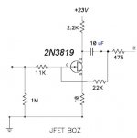
In Post #579: tschrama suggested that the gain could be increased to 5.5dB with a gate stopper resistor increased to 11k and the feedback resistor increased to 22K.
In post #583 : tschrama posted a schematic of this, but showed a 2N3819 in place of the 2SK170 (see below).
I think the NE5524 is configured for a gain of about 2 in my CD player (Rotel RCD965BX with SAA7323 DAC).
My question is, can I use the modified JBOZ, as posted by tschrama in post #583, to replace the NE5534 and output stage? My CD player is heavily modified and I have only a 10uF Black Gate and a 47R resistor in the signal line between the 5534 and the RCA connector. No muting ransistors or filter networks. I plan to run the JBOZ at +16V.
Do I need to make any changes to the tscharma modified JBOZ to use it as CD analog out? (I would use a 2SK170 instead of the 2N3819 shown)
Best regards,
Joe
Hello,
I would like to replace the NE5534, single op-amp in the analog out of my CD player, with the appropriate version of the JFET BOZ. However, the BOZ output may be too high for my original BOZ driving a DIY (Andrea Ciuffoli's 2005 Power Follower) SE MOSfet amp.
I have read through the tread looking for discussion on the particular topic of lowering the JBOZ gain and discovered the following posts:
Post #280 : In response to a question about JBOZ as a unity gain buffer, Zen Mod suggested changing the gate stopper resistor to 10K and adding another 10K resistor from the gate to the outside of the output cap.
In Post #579: tschrama suggested that the gain could be increased to 5.5dB with a gate stopper resistor increased to 11k and the feedback resistor increased to 22K.
In post #583 : tschrama posted a schematic of this, but showed a 2N3819 in place of the 2SK170 (see below).
I think the NE5524 is configured for a gain of about 2 in my CD player (Rotel RCD965BX with SAA7323 DAC).
My question is, can I use the modified JBOZ, as posted by tschrama in post #583, to replace the NE5534 and output stage? My CD player is heavily modified and I have only a 10uF Black Gate and a 47R resistor in the signal line between the 5534 and the RCA connector. No muting ransistors or filter networks. I plan to run the JBOZ at +16V.
Do I need to make any changes to the tscharma modified JBOZ to use it as CD analog out? (I would use a 2SK170 instead of the 2N3819 shown)
Best regards,
Joe
Attachments
Re: JBOZ as CD analog out
use original Papa's schematic
put trimer pot of 3k3 instead source resistor
connect just one channel and twiddle pot until you are satisfied with gain
measure resistance of pot , then place resistor of nearest standard value in both channels
that's called source degeneration - fancy word for "local feedback"
jnewbold said:Hello,
.......
Joe
use original Papa's schematic
put trimer pot of 3k3 instead source resistor
connect just one channel and twiddle pot until you are satisfied with gain
measure resistance of pot , then place resistor of nearest standard value in both channels
that's called source degeneration - fancy word for "local feedback"
Thanks Zen Mod. I will try this in the next couple of days. Have to wait for delivery of 2SK170s.
Joe
Zen Mod said:
use original Papa's schematic
put trimer pot of 3k3 instead source resistor
connect just one channel and twiddle pot until you are satisfied with gain
measure resistance of pot , then place resistor of nearest standard value in both channels
that's called source degeneration - fancy word for "local feedback"
Hi Zen Mod,
While I am waiting for JFET to arrive, I have another question about using the JBOZ to replace a NE5534 op-amp in a CD analogue output stage. If I put a 3k3 trimmer pot instead of the 10R source resistor to adjust the gain, as you recommend, can I remove the 25K pot on the input?
Regards,
jnewbold said:
Hi Zen Mod,
While I am waiting for JFET to arrive, I have another question about using the JBOZ to replace a NE5534 op-amp in a CD analogue output stage. If I put a 3k3 trimmer pot instead of the 10R source resistor to adjust the gain, as you recommend, can I remove the 25K pot on the input?
Regards,
even better -you can put 2k2 trimmer (my typo was 3k3) ;
yes - you don't need pot , but leave 1M resistor in place
watch that you don't connect DC on input of Jfet BOZ
Zen Mod said:watch that you don't connect DC on input of Jfet BOZ
I hadn't givent the DC from the DAC any thought. The schematics shows the external op-amp connected directly from the DAC's internal op-amps, so there may not be any DC on the input of the external op-amp. However, I will measure later today and add a cap if there is any DC present.
Just another two questions. If (when) the JBOZ is successful as a CD analogue output, can I then remove the input cap on my original BOZ pre-amp? I don't use any other sources and, in fact, my original BOZ has only one set of input RCAs.
Or, thinking about this a bit more, perhaps I can use the JBOZ as posted by NP (without 25K pot and with the 10R source resisitor) as a high gain CD output and bypass BOZ pre-amp direct to amp, via either a passive pot or a B1 Buffer?
Thanks again,
jnewbold said:
I hadn't givent the DC from the DAC any thought. The schematics shows the external op-amp connected directly from the DAC's internal op-amps, so there may not be any DC on the input of the external op-amp. However, I will measure later today and add a cap if there is any DC present.
......
correct ;
jnewbold said:
Just another two questions. If (when) the JBOZ is successful as a CD analogue output, can I then remove the input cap on my original BOZ pre-amp?
yes ;
jnewbold said:
.........
Or, thinking about this a bit more, perhaps I can use the JBOZ as posted by NP (without 25K pot and with the 10R source resisitor) as a high gain CD output and bypass BOZ pre-amp direct to amp, via either a passive pot or a B1 Buffer?
........
you can try that , but success really depends of what are demands for driving your power amp
Zen Mod said:watch that you don't connect DC on input of Jfet BOZ
Checked DC at input in of NE5534 and measured 2.56V, so will have to use a cap at input of JBOZ. Should ther cap be placed after 1M resistor and in series with 1K?
jnewbold said:
Checked DC at input in of NE5534 and measured 2.56V, so will have to use a cap at input of JBOZ. Should ther cap be placed after 1M resistor and in series with 1K?
1M is here to keep gate of poor little critter on gnd potential ........ and when current through source resistor is flowing ....... poor critter is suddenly self biased
") (via difference often called Ugs , or potential between gate and source )
(via difference often called Ugs , or potential between gate and source )so - leave 1M near gate , 1K where it belongs , and place needed cap between nasty DAC and cheerful JFet BOZ
so - I presume that you never tried actually drawing some new puzzle ?
believe me - much more fun than just solving bought one ........
download all Papa's pdfs you can find on his webs , and read ; believe me - more you read them , you'll be more laughing .......
- Home
- Amplifiers
- Pass Labs
- Jfet BOZ