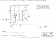
A co-worker of mine sent me a link to this schematic.
It looks pretty nice and I was wondering about this being my first P2P tube project.
Any thoughts about this?
I have built a couple of PCB based tube projects before and would be comfortable with building two of these.
My main concern is the real world application for this and it's usefulness.
Any input is much appreciated.
Attachments
My main concern is the real world application for this and it's usefulness.
Any input is much appreciated.
That is an excellent question. Too much gain for a modern line amp. Headphne amp, maybe? (still too much gain)
If you do have a use for a flat gain block, be careful of heater to cathode voltages- you'll want to elevate them to 50-60V above ground or so. And yes, like jgray said, you absolutely need a coupling cap on the output unless the next stage doesn't mind 125VDC pounding in!

My only thought for this would be to integrate it with my F4 as the driver stage all in one chassis.
I believe this would have plenty of gain for that application.
The original schematic had a capacitor at the output but it was integrated into a balance transformer circuit, I would add a few uF on the output of this.
I was thinking about subbing in 6CG7's for the 12BH7's.
Do you think it is a sound design for my application?
Last edited:
Yes, it could work for that. Likewise, you could use an ImPasse, bypassing the plate resistor on the cathodyne (which converts it to a cathode follower). About the same complication level.
6CG7 should work fine for the White CF. I think that you could do better with a higher transconductance tube, though.
6CG7 should work fine for the White CF. I think that you could do better with a higher transconductance tube, though.
My only thought for this would be to integrate it with my F4 as the driver stage all in one chassis.
I believe this would have plenty of gain for that application.
The original schematic had a capacitor at the output but it was integrated into a balance transformer circuit, I would add a few uF on the output of this.
I was thinking about subbing in 6CG7's for the 12BH7's.
Do you think it is a sound design for my application?
There is a problem with using this with an F4, it will come up to operating temperastures quite slowly and will create a temporary but significant DC offset on the F4 output - even with an interstage coupling cap. With very sensitive speakers this can be enough to overheat them. Even if this is not so it will at least produce a loud pop.
A timed relay between the stage with the preamp grounded for 10secs should be sufficient to overcome this.
Shoog
Imagine what happens to someone touching it, thinking that it's a few volts at most on the output.... you absolutely need a coupling cap on the output unless the next stage doesn't mind 125VDC pounding in!
Imagine what happens to someone touching it, thinking that it's a few volts at most on the output.
Don't blame Jensen for this. I didn't think Bill would be so stupid as to publish the schematic as represented here, so I looked at the original. It not only includes a coupling cap, but *surprise* an output transformer. It was rather irresponsible to edit the original and leave the output coupling cap out.
se
Attachments
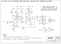
The gain starts to look quite sensible now. Should be a very good little line driver.Don't blame Jensen for this. I didn't think Bill would be so stupid as to publish the schematic as represented here, so I looked at the original. It not only includes a coupling cap, but *surprise* an output transformer. It was rather irresponsible to edit the original and leave the output coupling cap out.
se
Shoog
One of my pet peeves is that a fair number of pentode circuits I've seen starve the pentode, running its plate current at a small fraction of the nominal data sheet values. This circuit is an example, and many of the classic push-pull circuits that use a pentode-triode dual in the front end also starve the front end pentode (the triode generally pulls phase inverter duty). Can anyone explian the rationale for doing this? It seems to me that the pentode will have higher transconductance and better linearity with higher bias current.
Comments?
For the circuit under discussion, I would be tempted to go all modern and solid state, and run an SS current source from B+ to the pentode plate, allowing a higher bias current while still enabling use of a decent value of plate load for good open loop gain.
For those who aren't familiar, the output of the Jensen circuit is a classic White cathode follwer, sort of a poor man's push-pull. The value of the top plate load resistor is generally set at ~ 1/gm, where gm is the transconductance of the bottom tube. This concept can also be used with sand-state devices.
Good point. I was just making light of how unsafe it was as shown. Never claimed Jensen would have published it. We all know how things get hacked up on the internet.Don't blame Jensen for this. I didn't think Bill would be so stupid as to publish the schematic as represented here, so I looked at the original. It not only includes a coupling cap, but *surprise* an output transformer. It was rather irresponsible to edit the original and leave the output coupling cap out.
se
WOW!!!
Those transformers are $137 each.
WAAAYY out of my price range.
What about using a pair of power switches having one for the preamp section and one for the F4?
Or how about one switch that will drive a time delay relay, Have the tube start first and the F4 after 45 seconds or so.
Those transformers are $137 each.
WAAAYY out of my price range.
What about using a pair of power switches having one for the preamp section and one for the F4?
Or how about one switch that will drive a time delay relay, Have the tube start first and the F4 after 45 seconds or so.
Good point. I was just making light of how unsafe it was as shown. Never claimed Jensen would have published it. We all know how things get hacked up on the internet.
And I wasn't intending to imply that you were claiming Jensen would have published it. I wasn't speaking so much directly to you as generally.
se
You want high gm, not high mu. Or not necessarily high mu.
Classic choice there is one of the ECC88 family: ECC88, 6922, E88CC, 6DJ8, 6KN8, something like that. There are some high gm Russian triodes like 6C45P which have a great reputation, but I haven't used them personally. Whichever you choose, make sure to bypass locally and use grid stopper resistors right at the grid pins- they're happy to act as oscillators, especially with 100% local feedback that you get with cathode followers.
Classic choice there is one of the ECC88 family: ECC88, 6922, E88CC, 6DJ8, 6KN8, something like that. There are some high gm Russian triodes like 6C45P which have a great reputation, but I haven't used them personally. Whichever you choose, make sure to bypass locally and use grid stopper resistors right at the grid pins- they're happy to act as oscillators, especially with 100% local feedback that you get with cathode followers.
One of my pet peeves is that a fair number of pentode circuits I've seen starve the pentode, running its plate current at a small fraction of the nominal data sheet values. This circuit is an example, and many of the classic push-pull circuits that use a pentode-triode dual in the front end also starve the front end pentode (the triode generally pulls phase inverter duty). Can anyone explian the rationale for doing this? It seems to me that the pentode will have higher transconductance and better linearity with higher bias current.
Comments?
Yes, I can explain it. This design uses a 6AU6. Here is what the spec sheet says;
The 6AU6A is a miniature sharp cutoff pentode primarily designed for use as a high gain radio frequency or intermediate frequency amplifier. Its low grid-plate capacitance and high transconductance make it especially suited for high frequency, wide band applications.
See what's missing there? It makes no reference to audio amplification at all. For the purposes described, you want to make the plate load as small as possible, and make up the difference with lots of Gm to get your gain. Otherwise, load C will compromise both the high frequency and bandwidth performance. For these applications, you're not concerned with harmonic distortion since there will be one or more LC tuners and/or BPFs in the signal chain to reject it.
Vid amps will typically use "small signal" pents with ratings more like small power finals, but with relatively enormous Gm's. For the really wideband apps, you find distributed amps which are a whole 'nother story.
For audio, you want linearity. For good linearity, you want to minimize plate current swing, since Gm follows plate current. Since: V= IR, for any given delta-V, your delta-I will be smaller the bigger you make R. The smaller your delta-I, the less Gm variance you have. Therefore, for audio, get that plate load up. That will mean, of course, that your Q-Point bias currents will be small (unless your DC rail voltages are silly huge) as it is in this case where Ip= 1.25mA (and I've seen small signal pents operated as low as Ip= 200uA) The reduced Gm is made up by the relatively larger Rp. You can still have higher gain than a triode can provide (and if you don't get the gain, then why bother -- just use a triode).
You will need a friendly, Hi-Z, Lo-C load, just as you would if using the small signal, high gain, current trickle triodes (12AX7, 6SL7, etc). These were designed to use large Rp's without having to resort to exaggerated DC rail voltages.
For the circuit under discussion, I would be tempted to go all modern and solid state, and run an SS current source from B+ to the pentode plate, allowing a higher bias current while still enabling use of a decent value of plate load for good open loop gain.
You would need to do that if driving a difficult load, especially a Hi-C load, to avoid the slew rate problem. That's not gonna happen here since the load is a CF.
- Status
- This old topic is closed. If you want to reopen this topic, contact a moderator using the "Report Post" button.
- Home
- Amplifiers
- Tubes / Valves
- Jensen P-P Cathode Follower