How do you think Jens will review this? I don't think he has been on the forum for years now. Maybe he doesn't even read any posts nowadays.
I had no idea he had dropped off from DIYaudio. I would imagine maybe due to raising a child combined with the last couple of years global financial problems. I know I have had a few life changes in the last 5 years that has kept me from this community. However, due to this being his board design, I will still request his permission to at least post these files on here for others and for future reference to be used or modified by the individual to be used without having to re-invent the complete Eagle files.
...the fact that he never wanted to share his original eagle design files, by fear that he would be giving out his eagle software serial number in the process, because he was under the impression that info was present in the files.
But that's not the case at all, so he was bigly wrong about that. I have been digging into such files many times over the years to manually fix issues caused by eagle when it didn't handle the back annotation properly, so then design files would end up unusable from that point. So I have many times done editing manually outside of eagle to fix things, and so I know what info about eagle is present in the files, and that is the eagle version, nothing more.
So he had no valid reason to be scared about his serial number being shared.
I actually can understand how someone would think such things and become paranoid.
I do remember someone on this forum asking him what PCB design software he used and his reply was that it was not a PCB software but a graphics software. I did some searching and found the graphics software that he might have been using is proprietary to a studio mixing equipment design company. This is precisely why most people cannot open the current gerbers downloaded from Delta Audio Wayback Machine website. These gerbers are not standard .plt photo plotter gerber files.
But anyway, from all the data from back then, when he was sharing some of the things, I was able to re-create pretty much the same designs in eagle, from scratch.
And since, I've made several iterations of improvements. Plus I've done a fair amount of tweaking on the way the ground planes were done, to make at least one plane more intact, so it's more of a real ground plane, with far fewer breaks in it.
The most significant improvements I've been after, were a more sensible thermal sensing scheme. Although I would like to move away from individual diodes altogether, I kept that principle but aimed for a better thermal sensing, not just about how it's "joined" but rather how long the thermal lag is, due to the overly long distance between the sensing diodes' junctions and the power devices' junctions.
For that build as mentioned in post #1572, the thermal joining can't be very good, with only small strips of each diode's case being pressed against the heatsink. Not a very efficient thermal joining. Not to mention the long thermal lag due to how far away from the power devices that sensing board is placed.
I made a variant of the improved version based on Jens' design, with smaller separate sensing boards, which are mounted right on top of power devices. This reduces the number of thermal junctions, by a lot, plus the thermal lag can hardly be any shorter, being that close to the power device's junction..
This is precisely why I would like to be able to offer these files in a more universal file format.
The different file formats would facilitate most of us to use these "as is" or importing to [chose your flavor of software], be it CATIA, AutoCAD, FreeCad, Eagle, DesignSpark, CAM software, etc.
I had no idea he had dropped off from DIYaudio.
No posts from him for many years now. So I think it's unlikely that he's even been lurking at all. It's highly likely your request for permission will fall in deaf ears.
without having to re-invent the complete Eagle files.
It's basically what I did, years ago. And made several variants, with improvements. Including some of the improvements he had been discussing and was planning to implement, but didn't because he then disappeared...
The different file formats would facilitate most of us to use these "as is" or importing to [chose your flavor of software], be it CATIA, AutoCAD, FreeCad, Eagle, DesignSpark, CAM software, etc.
That is a hard thing to do, with so many packages in use out there. Very hard to have something universal.
Plus CAD isn't quite the same as ECAD.
I think many of us do use eagle though. As far as I know.
The thing is, if you're putting out files in a format such as gerber, then although it's pretty much universal, more or less, for having boards made, that format is a dead end and will not allow any further design updates. Plus many don't even have a gerber viewer anyway. And gerber doesn't show anything about the schematic and other things, only the raw pcb, for fabrication, nothing more.
If a proprietary ECAD file converted to a Gerber X2 then imported into Gerber Viewer software and converted to a CAD .dxf file and offered as a .dxf for further personal editing in CAD software then exported as a .bmp/.pdf/.jpg for others to use. Either directly import the image file into your preferential ECAD software, (yes I have imported the test.bmp file into Eagle and from Eagle to DSPCB), or edit in an image software (windose paint/Adobe PS/Adobe/Fireworks/CorelDraw), then import the .bmp , then export as gerber for boardhouse ordering or simply use that image file DIY thermal transfer/chemical etch.
Files to be offered for others to use:
1) Universal AutoCAD.dxf maybe even .step for 3D printers???
2) Editable and importable image file (several types of file formats including non-editable PDF).
3) The ability to export to whatever file format of the users fancy.
4) Gerbers of any flavor would only be offered if, IF, the user does not have the ability to download and use freeeeeee ECAD software and would like to use the available specified Gerber file types to be sent to their own boardhouse of their choosing.
What part of that process is not universal?
Does this give us the ability to convert a previously non-workable solution into a functioning workaround?
Yes.
Is this the long way around the mountain?
Yes.
This has nothing to do with production 'time savings' as this we all know too well is our hobby.
While you are correct ECAD and CAD software are not the same they can be used to convert files interchangeably with graphics softwares (ex. Adobe PS or Adobe Fireworks.
Why else would ECAD software be able to export a graphics image of your personal board file? Just to 'show-n-tell' your board? I present an option to be able to import a bmp image into Eagle then either trace over that or use other software to modify the board.bmp image or simply export it to be used in another form of software.
Your non-universal point is invalid.
Most convertable file types can become universal. It all depends on how you approach a problem and define the answer.
And furthermore, gerber is not natively universal unless you specify the type of gerber flavor used. (ex. Gerber X2, Gerber RS-274-X, Gerber RS-274-D)
Gerber X2 is photo plotter G-Code (x,y coordinates with arperature open or closed {process for presensitized UVpcb material})
Gerber RS-274-X gets converted to standard 3Axis CNC G-Code (x, y & z with feed rate and spindle rpm {process for routing/milling})
A photoploter can not read 3Axis G-Code and visa-versa a 3Axis CNC can not read photoploter G-Code.
And in the spirit of DIYaudio would you happen to be able to offer your modified design files that you have improved upon?
Or are your files proprietary for commercial sales?
If it is the later, I respect the fact that you are selling your modified Jens/Leach amps.
Last edited:
Does anyone have a set of calipers and at least 1 of Jens boards?
As long as I can get within 0.5mm or 0.020 inch.
#1) Approximate width of any of the output transistor tracks
#2) Approximate width of any of the signal tracks
#3) Approximate width of the isolation gap.
As long as I can get within 0.5mm or 0.020 inch.
#1) Approximate width of any of the output transistor tracks
#2) Approximate width of any of the signal tracks
#3) Approximate width of the isolation gap.
Last edited:
Jens designed this using eagle, and eagle has trace widths that are established and even if you're not able to precisely measure traces, a very rough measurement will be close enough to a known trace width among the defined ones, so that part of it shouldn't be too tricky to figure out.
However, it's a serious job to go through all that stuff, and what is best to arrive at, is a fully editable MCAD design.
As mentioned a couple of posts earlier, there were quite a few variants that came out from Jens, and so the question is more of "which one" to choose.
I have recreated several of his designs back then, in eagle, and made variants from there.
I'm not paranoid as he was with sharing the native eagle files, and the whole purpose of the forums is the sharing, so of course I'm game about sharing it all. And I've done far more than simply redoing it in eagle, as I've also done CAD along with it, to have illustrations to help build things. Now since there are so many variants and not everyone wants to go after the same one, I guess I could post a sample of one that might be among the most popular, and see where that goes.
I'll post the eagle files and some visuals next...
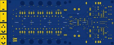
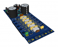
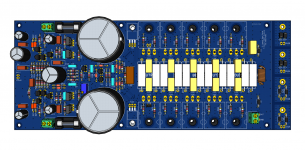
Here is one of my Jens based variants, for a 5 output pairs, with the thermal sensing board changes that I've been tweaking to improve.
I'm still using eagle v6.1, quite old, but works.
I'm posting this one because it's the only one so far that has been actually made by a board house, so the gerbers have been used and accepted by them.
Plus someone is working on building a few right now, and he's even sent me a few bare boards, which look super nice.
I didn't rewrite Jens' excellent build document, with the bunch of maths and all that, because although there were many tweaks and some changes made on this variant compared to his, it's still worth using his build info as a guide, because it still mostly applies.
Now as I mentioned, I also did some cad along with this, and I can post some more visuals next. This may be of interest to some amp builders who are mostly at a dead end wanting to build a leach designed by Jens but don't have original MCAD files to do more work on it and put out updated gerbers.
Attachments
Going with my previous post, here are some more outputs for this leach build:
I had to compress (zip) one of the pdfs, because the file size exceeded the forum's limit.
I had to compress (zip) one of the pdfs, because the file size exceeded the forum's limit.
Attachments
-
TH2 PCB assy.PDF757.6 KB · Views: 106
-
TH2 PCB assy detail.PDF967.8 KB · Views: 116
-
Main PCB+HS Assy.PDF1.1 MB · Views: 115
-
 leachamp4_5_board_bottom.jpg848.4 KB · Views: 235
 -
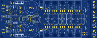 leachamp4_5_board_top.jpg1.1 MB · Views: 242
 -
TH3 PCB assy.PDF674.6 KB · Views: 103
-
Main PCB+HS Assy Mounting holes & taps.PDF.zip2.1 MB · Views: 114
Jens put a lot of work into his builds, with great care. And then he pretty much disappeared. Which was unfortunate, because he never shared any of the actual design files, so all we had were outputs, but nothing further alterable to tweak the design further.
And when many of the files also disappeared, we're left with whatever was saved by some users and what was posted here and there. Leaving us with a desire to build those things but not always quite enough to work with to do so.
Anyway, I also did spend quite a bit of time in recreating his lost work, and added some more to it. Hopefully something to continue working on from now on... And I'm sharing the design files, so nothing to block anyone from attempting builds..
I made a hi res. scan of my pcb's and made a pdf file of the scan. If one displays this on a PC monitor you can zoom in many times and with a few known dimensions of the pcb you can exactly measure the several sizes. But the file is 6.2 Mb and to big to place here.
Regards, Loek
Regards, Loek
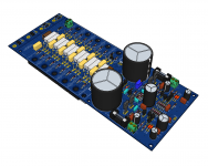
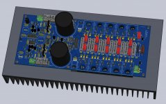
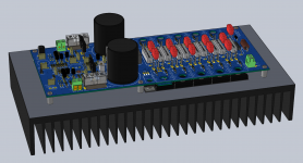
Here are a few more files for the build posted a few posts above.
The board is almost the same size as Jens' original, except for a tiny length difference due to the smaller different thermal sensing boards.
The board is almost the same size as Jens' original, except for a tiny length difference due to the smaller different thermal sensing boards.
Attachments
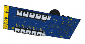
Although a few caps are missing in this assembly, here are a couple more 3D views from an assembly put on a Conrad Heatsink, which was used to make the 2D drawings with dimensions posted earlier.
Attachments
Man, I haven't listened to mine in a long time now. The case I built is very heavy. 1/4" aluminum for the top bottom and back and 3/8" front panel. The heatsinks are 10" x 9 1/2" x 2 1/2". This thing is heavy so I ended up out of my stack. I need to put it back so I can listen to it once in a while. Same with my Leach Superamp. It is out of the loop too. Those are some killer amps. That deserve to get warmed up from time to time.
Blessings. Terry
Blessings. Terry
Man, I haven't listened to mine in a long time now. The case I built is very heavy. 1/4" aluminum for the top bottom and back and 3/8" front panel. The heatsinks are 10" x 9 1/2" x 2 1/2". This thing is heavy so I ended up out of my stack. I need to put it back so I can listen to it once in a while. Same with my Leach Superamp. It is out of the loop too. Those are some killer amps. That deserve to get warmed up from time to time.
Yeah man! I've seen your builds, and you make them tough like a tank.

You've made so many, and there is no way you could ever make use of them all at once, so I bet you put some away and forget you have them sometimes.
Dust them up and give em a whirl!
And if they've been away for too long, it's probably time to think about re-cap...
I have some vintage amps, commercially built, from back when before I started making amps (in the 70s), and I've been planning a full re-cap on them, before powering them up. Those are old classic, nothing like the leach though..
Yeah man! I've seen your builds, and you make them tough like a tank.
You've made so many, and there is no way you could ever make use of them all at once, so I bet you put some away and forget you have them sometimes.
Dust them up and give em a whirl!
And if they've been away for too long, it's probably time to think about re-cap...
I have some vintage amps, commercially built, from back when before I started making amps (in the 70s), and I've been planning a full re-cap on them, before powering them up. Those are old classic, nothing like the leach though..
Yes, I should probably reform the filter caps before I fire it up. Hopefully the caps on the PCB will be alright. It doesn't have a lot of hours on it.
It's not really the actual hours of function that makes those caps age, it's just time.
So if they're old, you should consider all of them, not just the big ones.
All electrolytics will have that aging problem, so better be safe than sorry.
It's preferable to avoid any of them blowing up.
The coupling caps may not be subjected to voltages and currents to cause them to blow up, but surely they may taint the sound.
- Home
- Group Buys
- Jens Rasmussen Leach clone group buy