As above, the 500 VA 40V transformer will certainly be adequate for single channel Leach operation unless you are planning to use it in a nightclub at full power continuously into low impedance loads.
It should also have adequate margin for your Krellclone monoblocks although some would suggest slightly larger. Again low impedance loads and high continuous power point towards a heavier transformer.
It should also have adequate margin for your Krellclone monoblocks although some would suggest slightly larger. Again low impedance loads and high continuous power point towards a heavier transformer.
AndrewT said:.......the 3pair PCB, gave 411W into 4r0 when mains was ~240Vac.
This would require a transformer between 400VA and 800VA for a single channel.....
can't you read?samoloko said:.....but If you have to do It with one transformer per channel for the same stereo amp what rating of transformer you will chose
what Is the formula
Missing feedback capacitor for v5.6.10 Leach pcb??
Hi All,
I was comparing the schematics of the various Leach amps we have been discussing, and I noticed that a pair of capacitors in the feedback loop from one pair of the output transistors back to the driver stage seems to be missing. In the latest schematic on Prof. Leach's web site, these are designated C19, C20 and are specified as 0.01 uF, 50 V film caps. These caps correspond to C301 and C302 on the new proposed combo board "Leach power stage." But on the older board, version 5.6.10 from Jens, I would expect to see a similar cap across R41 and R62, and I don't find it. Am I missing something, or isn't it needed in that version??
Best wishes,
Keith
Re: Missing feedback capacitor for v5.6.10 Leach pcb??
Prof. Leach about "Low TIM Amplifier" wrote:
"...A current limiting circuit can be inherently unstable and cause oscillations under limit conditions. This can be understood by a simple heuristic argument. Once an overload occurs, the limit circuit is triggered, and the overload condition is eliminated. This cause the limit circuit to deactivate, at which time the overload condition reappears. This is a vicious cycle which can manifest itself as oscillations. Capacitors C15 and C16 help prevent this problem in the VI limiter of Fig.1. In addition, the limiter threshold is set so that it is improbable that the limiting function wil be activated under normal signal and load conditions."
Audio, February 1977
C15, C16 in "Low TIM Amplifier" is same as C19, C20 in original "Leach Amp" or C35, C42 in version 7.4.6 from Jens
Hi,kpmadden said:Hi All,
I was comparing the schematics of the various Leach amps we have been discussing, and I noticed that a pair of capacitors in the feedback loop from one pair of the output transistors back to the driver stage seems to be missing. In the latest schematic on Prof. Leach's web site, these are designated C19, C20 and are specified as 0.01 uF, 50 V film caps. These caps correspond to C301 and C302 on the new proposed combo board "Leach power stage." But on the older board, version 5.6.10 from Jens, I would expect to see a similar cap across R41 and R62, and I don't find it. Am I missing something, or isn't it needed in that version??
Best wishes,
Keith
Prof. Leach about "Low TIM Amplifier" wrote:
"...A current limiting circuit can be inherently unstable and cause oscillations under limit conditions. This can be understood by a simple heuristic argument. Once an overload occurs, the limit circuit is triggered, and the overload condition is eliminated. This cause the limit circuit to deactivate, at which time the overload condition reappears. This is a vicious cycle which can manifest itself as oscillations. Capacitors C15 and C16 help prevent this problem in the VI limiter of Fig.1. In addition, the limiter threshold is set so that it is improbable that the limiting function wil be activated under normal signal and load conditions."
Audio, February 1977
C15, C16 in "Low TIM Amplifier" is same as C19, C20 in original "Leach Amp" or C35, C42 in version 7.4.6 from Jens
Congratulations, you found an oversight that nobody else picked up in two years of building this amp.
Since nobody seems to have complained that their amp behaves strangely in protection, it's probably safe to assume that the caps are not strictly necessary. Further into the quoted section Prof. Leach mentioned that bypassing all of the sense resistors caused undesirable behavior.
If you are worried about oscillation in and out of protection (you probably don't need to be for home use), you have two options:
1. Leave protection out completely. Not too unreasonable given how rugged the output stage is usually built and if care is taken to avoid shorting the outputs
2. Place the 10 nF caps across R42 and R62 on the bottom of the board.
You may also have noticed that Jens has added all of the output stage coupling caps, which I believe helps stabilize the amp, to each output bjt.
The main question which always puzzled me was raising the rail voltages so far above the Low Tim amps original specs. Is the adjustment for rail voltage at R3, R22 to keep the protection circuit in check or some other function? My current amp seems to be quite stable and unoffensive at very high volume pushing 70+ volts on the rails. Just how high could the rails be pushed in this current design before design changes are implemented?
Seems Dr. Leach covered most of the bases quite well 25 years ago.
Tad
R3 and R22 set the current in the zeners that are the cascode voltage references (D1-4). The other current flowing through them is the opposite differential pair and one leg of the same side differential. Those currents are set by R5 and R20.
At higher rail voltages you'd pump more current into the zeners and possibly exceeding their dissipation ratings if you didn't increase R3 and R22.
I'm not sure that I'd use the word stabilize, as it usually refers to an amp's ability to avoid oscillation. The film decoupling caps probably help keep signal and noise off the rails and clean up the output. It would be interesting to hook the amp up to an Audio Precision with and without them to see if they have a measurable effect. (Carl?)
Any interest in theseHeat Sinks/Group Buy?
Hello all.
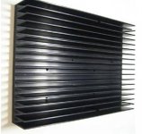
I was wondering if anyone here would be interested in a group buy for some nice, new black anodized heat sinks.
I've located some nice ones, measuring 5.25"Wx7.5"Hx1.25"deep(fins are >1" long).
One could use a pair of these , side by side for each channel of a 100-120W Leach amp...
The cost will be approx $8 each, so around $32 for a stereo amp, plus postage.
If anyone is interested, please send me a private message.
Thanks,
-chas
Hello all.
I was wondering if anyone here would be interested in a group buy for some nice, new black anodized heat sinks.
I've located some nice ones, measuring 5.25"Wx7.5"Hx1.25"deep(fins are >1" long).
One could use a pair of these , side by side for each channel of a 100-120W Leach amp...
The cost will be approx $8 each, so around $32 for a stereo amp, plus postage.
If anyone is interested, please send me a private message.
Thanks,
-chas
Attachments
Hello everybody,
i have a question about the resistors used in this project. I have some PRP 1/2W (the red ones) at home but they are just a bit too large and so i cannot use them.
In the list of materials all the resistors are specified for 0.6W but is that necessary? Maybe some 0.25W would be enough?
If i use the specified 0.6W what brand is the right dimension?
Sorry for my english, Regards,
Boris
kraljmatjaz said:If i use the specified 0.6W what brand is the right dimension?
Looking for metal film 0.6W resistor. Size code 0207. They are on sale Distrelec for example Vishay MBB/SMA 0207, Elfa.se - Firstronics RM0207, Digikey - Vishay MRS25 and etc.
kraljmatjaz,
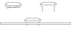
I'm using the same PRP resistors. Just bend the leads under, then down to fit (see illustration). IMHO, these(and the Holco's) are better sounding resistors than the small generic metal films I've found.
Just be careful to use fine needlenose pliers or a lead bending jig to avoid stressing the leads where they attach(especially with the original Holco units).
Happy Holidays!
-chas
I'm using the same PRP resistors. Just bend the leads under, then down to fit (see illustration). IMHO, these(and the Holco's) are better sounding resistors than the small generic metal films I've found.
Just be careful to use fine needlenose pliers or a lead bending jig to avoid stressing the leads where they attach(especially with the original Holco units).
I have some PRP 1/2W (the red ones) at home but they are just a bit too large
Happy Holidays!
-chas
Attachments
found a power AMP case from China's DIY sitehttp://www.lite8.com/product.php
It's net weight is 15KG with heat sink
Looks nice for under 120W/channel, BUT-
You may wish to check the freight charges , as they may easily double the cost of the item!
-chas
Bob Ellis said ...
"I'm not sure that I'd use the word stabilize, as it usually refers to an amp's ability to avoid oscillation. The film decoupling caps probably help keep signal and noise off the rails and clean up the output. It would be interesting to hook the amp up to an Audio Precision with and without them to see if they have a measurable effect. (Carl?)"
Sorry for being so slow in responding. Quality film bypass caps are very important to this amplifier. To prove this to yourself simply monitor the power rails with a quality 200 mHz scope without the bypass caps in place. If your amplifier isn't already oscillating, you will be amazed at the garbage that finds its way from your house mains and into your amplifier. Don't bother buying a fancy power cord. There is no empirical evidence that it would make a difference. Instead buy quality bypass caps and install them at every opportunity.
buy quality bypass caps and install them at every opportunity
Carl: What do you recommend for the bypass caps?
If the excellent quality 0.1uf caps I have found are too large to fit, how much smaller a value of premium caps will still be helpful?
-Joe
- Home
- Group Buys
- Jens Rasmussen Leach clone group buy