Hello Jean-Michel,
Yes, I've noticed too that phase is ambiguous at low freqs because of room reflections.
But then the group delay picture you posted earlier is calculated as a derivative of a phase curve. How accurate this is I have to question? What was the measurement distance, is it measured at the mouth?
Yes, I agree. Time - frequency plots are most useful. Especially when looking at the room efects.
If this kind of belief is common, I think this is due to fact that previously basically all home speakers have been monopoles without any directive at low frequencies. If there is no low frequency directivity on cannot have accurate reproduction neither of amplitude nor phase in a room. Dipoles have directivity, also horns do if they are big enough compared to the wavelength. That is one reason they behave better in a room than monopoles.
Would it be possible to have this spectrogram plot
http://www.diyaudio.com/forums/attachment.php?s=&postid=1838422&stamp=1243414513
to be viewed in a time scale of periods, not the linear time? Then it would be more clear how the room affect the sound.
- Elias
Jmmlc said:When it comes to propagating waves considering values of phase in an absolute way is pretty much useless.
Yes, I've noticed too that phase is ambiguous at low freqs because of room reflections.
But then the group delay picture you posted earlier is calculated as a derivative of a phase curve. How accurate this is I have to question? What was the measurement distance, is it measured at the mouth?
IMHO what is more important is how energy is liberated inside a frequency / time plane. That's why I give some importance to CSD (...sonograms, waterfall, spectrograms....)
Yes, I agree. Time - frequency plots are most useful. Especially when looking at the room efects.
We are so accustomed since decades to read that correct phase reproducing of low frequency signals (e.g. : f < 200Hz) is useless because the room destroys any phase relationship at those frequencies... it beacame very rare someone questions the veracity of such postulate.
If this kind of belief is common, I think this is due to fact that previously basically all home speakers have been monopoles without any directive at low frequencies. If there is no low frequency directivity on cannot have accurate reproduction neither of amplitude nor phase in a room. Dipoles have directivity, also horns do if they are big enough compared to the wavelength. That is one reason they behave better in a room than monopoles.
Would it be possible to have this spectrogram plot
http://www.diyaudio.com/forums/attachment.php?s=&postid=1838422&stamp=1243414513
to be viewed in a time scale of periods, not the linear time? Then it would be more clear how the room affect the sound.
- Elias
Hello
IMHO we should not consider dipole as loudspeakers having high directivity, specifially in the low frequency range.
We have 2 consider monopole as a couple of 2 monopoles emitting in opposite polarity (inverted phase). Each monopole (front and rear) has no directivity at all at low frequency. It is only due to the acoustic short circuit (may be in English the correct expression is "short cut") resulting from the interference of the 2 monopoles that some directivity is obtained "in practice". But anything (room...) that acts as a perturbation of that interaction between the non directive rear wave and the non directive front wave, impacts the apparent directivity of that "dipole".
In fact this lead to a quasi useless of dipoles in the VLF (very low frequency). I once gave the example of the Infraplanar as a perfect illustration of that. (the only good use of such loudspeaker should be in infinite baffle)
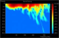
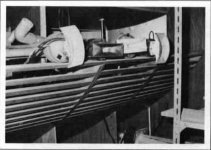
You'll find in attached file a burst decay of the pulse response of the bass horn belonging to Jean-Paul.
Best regards from Paris, France
Jean-Michel Le Cléac'h
IMHO we should not consider dipole as loudspeakers having high directivity, specifially in the low frequency range.
We have 2 consider monopole as a couple of 2 monopoles emitting in opposite polarity (inverted phase). Each monopole (front and rear) has no directivity at all at low frequency. It is only due to the acoustic short circuit (may be in English the correct expression is "short cut") resulting from the interference of the 2 monopoles that some directivity is obtained "in practice". But anything (room...) that acts as a perturbation of that interaction between the non directive rear wave and the non directive front wave, impacts the apparent directivity of that "dipole".
In fact this lead to a quasi useless of dipoles in the VLF (very low frequency). I once gave the example of the Infraplanar as a perfect illustration of that. (the only good use of such loudspeaker should be in infinite baffle)
You'll find in attached file a burst decay of the pulse response of the bass horn belonging to Jean-Paul.
Best regards from Paris, France
Jean-Michel Le Cléac'h
Elias said:Hello Jean-Michel,
If this kind of belief is common, I think this is due to fact that previously basically all home speakers have been monopoles without any directive at low frequencies. If there is no low frequency directivity on cannot have accurate reproduction neither of amplitude nor phase in a room. Dipoles have directivity, also horns do if they are big enough compared to the wavelength. That is one reason they behave better in a room than monopoles.
http://www.diyaudio.com/forums/attachment.php?s=&postid=1838422&stamp=1243414513
to be viewed in a time scale of periods, not the linear time? Then it would be more clear how the room affect the sound.
- Elias
Attachments
Jmmlc said:Hello
IMHO we should not consider dipole as loudspeakers having high directivity, specifially in the low frequency range.
We have 2 consider monopole as a couple of 2 monopoles emitting in opposite polarity (inverted phase). Each monopole (front and rear) has no directivity at all at low frequency. It is only due to the acoustic short circuit (may be in English the correct expression is "short cut") resulting from the interference of the 2 monopoles that some directivity is obtained "in practice". But anything (room...) that acts as a perturbation of that interaction between the non directive rear wave and the non directive front wave, impacts the apparent directivity of that "dipole".
In fact this lead to a quasi useless of dipoles in the VLF (very low frequency). I once gave the example of the Infraplanar as a perfect illustration of that. (the only good use of such loudspeaker should be in infinite baffle)
You'll find in attached file a burst decay of the pulse response of the bass horn belonging to Jean-Paul.
Best regards from Paris, France
Jean-Michel Le Cléac'h
If you have a directive rear wave formed into a cardioid you can have near directivity of the horn in the bass (not low bass!) and take up less space in the room. It can also sound less colored then a bass horn if used in the same range and of course have wider bandwith at the expense of efficiency. Forming a system with multiple cardioids (3-4 high efficiency 15's) can be pretty efficient though, and can be even more directional.. Nothing will beat a full sized horn but to integrate it with the rest of the music range and fit it "through the door" is many other problems. If the horn is not full size then you must precisely place the horn in the room to obtain the compromised directivity and compromised full benefit. Not many will use a full (or half!) size horn
>> If you have a directive rear wave formed into a cardioid you can have near directivity of the horn in the bass (not low bass!) and take up less space in the room.
I am thinking about this for quite a while, too (with 3"-FR-drivers). Probably, for fexibility in experimenting, I'd not use the backwave directly but rather a seperate driver (inverted polarity), both working with closed rear chambers. And all digital/active design, for utmost flexibility (delays, indendent EQing etc). Plus a classical cardiod bass/sub extension...
Are there any working solutions of the principle we could look at? I'm pretty curious
- Klaus
Jmmlc said:Hello
IMHO we should not consider dipole as loudspeakers having high directivity, specifially in the low frequency range.
I agree - but was puzzled by the uniform coverage of this monsters over the entire room - and especially from what I thought would be a non optimal placement
http://www.mfk-projects.com/home_theatre.htm
http://www.mfk-projects.com/theatre_woofer.htm
By the way the double horn still is top notch in my rating - I'm very happy with its presentation - though I possibly try some slight variations (seems I can't resist to give soongsc approach a try) - will see...
Michael
Hello,
I didn't catch what was the measurement distance, is it measured at the mouth or at the listening position?
- Elias
I didn't catch what was the measurement distance, is it measured at the mouth or at the listening position?
- Elias
Originally posted by Jmmlc
You'll find in attached file a burst decay of the pulse response of the bass horn belonging to Jean-Paul.
Hello Elias,
I think that the mesurement of Jean-Paul's bass horn is performed at a distance of 2 meters of the mouth as the following curves:
http://zepload.com/images/1242489777_estrade D 0cm & cor.jpg
red = without equalization
blue= with equalization below 45Hz
same but without equalization and showing the distortion components:
http://zepload.com/images/1242565693_Disto 0cm estrade sans cor.jpg
red = H2 (note: measurement preformed with an electret with fet preamp having non negligeible H2 level)
blue = H3
Here is a measurement of the whole system at the listening position
http://zepload.com/images/1242490197_G & D ze.jpg
yellow = left channel
red = right channel
Best regards from Paris, France
Jean-Michel Le Cléac'h
Elias said:Hello,
I didn't catch what was the measurement distance, is it measured at the mouth or at the listening position?
- Elias
JMLC, what you think is the maximum usable bandwidth of horns of your style - and - is there a big difference to other types of horns in this?
If I take my double horn that starts somewhere at 1kHz and goes up to somewhere slightly aove 10kHz *without* any irregularity - is this a usual bandwidth?
Michael
If I take my double horn that starts somewhere at 1kHz and goes up to somewhere slightly aove 10kHz *without* any irregularity - is this a usual bandwidth?
Michael
Hello Michael,
Axisymetric Le Cléac'h horns if they are built with a complete mouth rollback provide a pure resistive loading to the loudspeakers since 1 octave or so from its acoustic cut-off. From this feature result :
1) a very wide frequency response (a Le Cléac'h horn having Fc = 320Hz loading a TD2001 shows flat unequalized response from 350Hz to 18000Hz)
2)a very low displacement of the membrane of the loudspeaker and thus very low distortion
3) a very pure impulse response
In your case as you use a quasi cylindrical wavefront horn (a type of horn devoted normally to very low frequency) the main limiting factor is diffraction at the horizontal edges of the mouth.
If you succeed in reducing this diffraction then you may obatin a flat response above 10kHz
Best regards from Paris, France
Jean-Michel Le Cléac'h
mige0 said:JMLC, what you think is the maximum usable bandwidth of horns of your style - and - is there a big difference to other types of horns in this?
If I take my double horn that starts somewhere at 1kHz and goes up to somewhere slightly aove 10kHz *without* any irregularity - is this a usual bandwidth?
Michael
Jmmlc said:
In your case, as you use a quasi-cylindrical wavefront horn (a type of horn devoted normally to very low frequency), the main limiting factor is diffraction at the horizontal edges of the mouth.
If you succeed in reducing this diffraction then you may obtain a flat response above 10 kHz.
Best regards from Paris, France
Jean-Michel Le Cléac'h
Quick thought: the limiting factor in Michael's quasi-cylindrical horn is the diffraction from the edges of the top and bottom plates. Michael, have you thought of using a random grid-pattern of holes drilled in the plates to act as a progressive loss or "soft edge" for the plates? Or a pattern of serrations on the front edge of the plates, instead of a straight-edge?
Either measure would diffuse and spread out the re-radiation of energy from the sharp edge of the plates.
Thanks for clarification Jean Michel
300-18k is about six octaves – very impressive - and way more than enough if I start form 1000Hz.
Just to check – in your axisymmetric horns there is no such notch like with mine corresponding to throat diameter?
As you possibly know I have built soongsc’s contour with about the same overall dimensions and got that irregularity slightly shifted towards higher frequencies.
The lip I (intentionally) used for these measurements are as straight as the ones for the original LeChleach contour (no sexy lips) but roughly 8cm 3” farer from the diaphragm – so I have options left for whatever edge treatment.
The main difference though – in my opinion until now was - that the throat is slightly narrower as soongsc built kind of compressor driver contour into the horn - or is this more kind of a diffraction horn contour – I really don’t know?.
The ratio of the two throat widths is roughly the difference in up-shift of the irregularity.
So I’m unclear in this respect – but definitely would like to throw in some effort to stretch pass band to well above 20k.
My guess was that the smaller the throat the higher the upper usable frequencies. I’m not sure but think I have seen very similar graphs elsewhere and soongsc’s has confirmed that he gets (roughly) the same irregularity with axysymmetric horns.
Here I try to explain what possibly has happened:
http://www.diyaudio.com/forums/showthread.php?postid=1854398#post1854398
Lynn – no, haven’t thought of drilling holes, yet – could do with no problem to give it a try though. What pattern would you suggest? I easily can glue whatever extension to the horizontal edge - the plates are roughly 20mm / 3/4 “ thick.
I intended to do measurements with the front edge elongated first with straight cut than with the sexy lips following the LeCleach wave front contour to see how this may affect FR over non axis angels.
Panomaniac, was that link for me – I can’t put it into context?
Michael
mige0 said:
Lynn – no, haven’t thought of drilling holes, yet – could do with no problem to give it a try though. What pattern would you suggest? I easily can glue whatever extension to the horizontal edge - the plates are roughly 20mm / 3/4 “ thick.
I intended to do measurements with the front edge elongated first with straight cut than with the sexy lips following the LeCleach wave front contour to see how this may affect FR over non axis angels.
Michael
A random pattern with the density of holes increasing towards the edge. Put another way, start with a few holes about halfway down, increase the number as it moves closer to the lip, and have lots closest to the edge. Make the holes small, less than 4-5 mm, and use a lot of them.
When Bjorn was doing BEM sims of the AH425, we were surprised at how fast loading disappeared as the T ratio increased. Some odd bumps started appearing in the acoustic impedance as well. As the T ratio went above 1, the acoustic-impedance bumps get bigger and bigger, and the overall loading in the 2~5X fc region decreased.
Based on the BEM simulations, the tradeoff between a LeCleac'h T=0.707 and a quasi-conical looked pretty straightforward; flat resistive loading down to cutoff, and a directivity pattern that looked like a medium-sized direct-radiator, versus somewhat uneven loading and a conical dispersion pattern (constant-directivity). Soongsc's horn appears to be transitional between the two types.
I'm thinking the ultimate HF limit is a function of the throat area - and the "squeeze" or "pinch" you sometimes see in the throats of prosound horns is nothing more than a trick to extend the bandwidth by a few kHz at the cost of diffraction and time distortion.
If you decrease the vertical size of the AMT ribbon (and the throat area), I'll bet the HF extension increases. The tradeoff is decreased headroom in the midrange due to loss of diaphragm area. Personally, I'd keep the diaphragm area - headroom and dynamic range are a good thing.
Hello Michael,
If one look to the on axis unequalized response curve of an axisymetric Le Cléac'h horn there is no such hole as with an axisymetric waveguide.
Eventually a small hole on the response curve may be seen at frequency over 14kHz and with angle over 15 degrees from the axis.
I attached a graph with frequency response curves at different angles for one of my TAD TD2001 mounted on a Le Cléac'h horn (Fc=320Hz T=0.8) applying on axis equalization.
Best regards from Paris, France
Jean-Michel Le Cléac'h
mige0 said:Thanks for clarification Jean Michel
Just to check – in your axisymmetric horns there is no such notch like with mine corresponding to throat diameter?
Michael
Attachments
KSTR said:Hi Lynn,
In his latest AES-paper, Angelo Farina ...Silence Sweep: a novel method for measuring electro-acoustical devices
Great, thank You. The method has to be discussed. Example given, with a wide range driver the lower frequencies modulating any other will clearly dominate the IM spectrum. That is the same issue as with the multitone signal.
Lynn Olson said:
I'm thinking the ultimate HF limit is a function of the throat area - and the "squeeze" or "pinch" you sometimes see in the throats of prosound horns is nothing more than a trick to extend the bandwidth by a few kHz at the cost of diffraction and time distortion.
Hi Lynn
I would completely agree with you here, its not only obvious from the products but it holds up to be true analytically. One has to be concerned with those things that are often done to "hold up" the high end.
For one customer, I was asked to use a TAD driver instead of the B&C on the OS waveguide. It worked the same at lower frequencies, but it dropped fairly rapidly at the upper octaves. The customer had trouble believing this and showed me data from Pioneer that had a fairly flat HF response. But looking at the horn that was used it was obvious that they had tailored the HF response to beam thus obscuring the true falloff of the power response. When looking only at a single axial curve one does not see these aspects of the problem.
Hello Earl,
Such drivers like TD2001 or TD4001 use a front Alnico magnet.
Alnico magnets are generally longer than other type of magnets.
Due to this required geometry, there is quite a long distance (6.5 centimeters) through the magnet from the output of the phase plug to the output of the driver ( = the throat of the horn).
http://www.pioneerelectronics.com/pio/pe/vgn/images/portal/cit_3442/35720TD-2001a_big.gif
For sure this limits the use of an OSwaveguide on a driver like the TD2001.
But I don't think this quasiconical part inside the driver itself is the responsible of the extended axial response as we can see when the driver is loaded by a Le Cléach horn e.g.. No simulation I could see explained why the axial response is so extended. (BEM, FEM, Hornresp...).
We are still looking for the reason why. I was thinking that may be the TD2001 doesn't deliver a flat front (may be its a constant phase front but not a constant pressure front).
Best regards from Paris, France
Jean-Michel Le Cléac'h
gedlee said:
Hi Lynn
I would completely agree with you here, its not only obvious from the products but it holds up to be true analytically. One has to be concerned with those things that are often done to "hold up" the high end.
For one customer, I was asked to use a TAD driver instead of the B&C on the OS waveguide. It worked the same at lower frequencies, but it dropped fairly rapidly at the upper octaves. The customer had trouble believing this and showed me data from Pioneer that had a fairly flat HF response. But looking at the horn that was used it was obvious that they had tailored the HF response to beam thus obscuring the true falloff of the power response. When looking only at a single axial curve one does not see these aspects of the problem.
Jmmlc said:Hello Earl,
Such drivers like TD2001 or TD4001 use a front Alnico magnet.
Alnico magnets are generally longer than other type of magnets.
Due to this required geometry, there is quite a long distance (6.5 centimeters) through the magnet from the output of the phase plug to the output of the driver ( = the throat of the horn).
http://www.pioneerelectronics.com/pio/pe/vgn/images/portal/cit_3442/35720TD-2001a_big.gif
For sure this limits the use of an OSwaveguide on a driver like the TD2001.
But I don't think this quasiconical part inside the driver itself is the responsible of the extended axial response as we can see when the driver is loaded by a Le Cléach horn e.g.. No simulation I could see explained why the axial response is so extended. (BEM, FEM, Hornresp...).
We are still looking for the reason why. I was thinking that may be the TD2001 doesn't deliver a flat front (may be its a constant phase front but not a constant pressure front).
Best regards from Paris, France
Jean-Michel Le Cléac'h
Very likely.
With that kind of phase plug one must be blue-eyed to assume that the outer cannulas provide the same ammount of volume throughput as the inner ones - given its diameters are roughly the same for all (which can't be seen in that tiny graph).
Its simply that the air has to change an additional 45deg or so in direction as the cannulas are roughly perpendicular to the membrane but the membrane simply isnt breathing .
Michael
Jmmlc said:Hello Earl,
Such drivers like TD2001 or TD4001 use a front Alnico magnet.
Alnico magnets are generally longer than other type of magnets.
Due to this required geometry, there is quite a long distance (6.5 centimeters) through the magnet from the output of the phase plug to the output of the driver ( = the throat of the horn).
Best regards from Paris, France
Jean-Michel Le Cléac'h
Hi Jean-Michel
I tend to look at it much simpler. The OS, being true CD, will exhibit the power response of the source on axis. If this falls then the power response has to be falling (we expect -6 dB as normal, but the TAD falls much faster than this at HF). This is most likely due to the mass and inductance of the diaphragm when compared to a driver like the DE250 which does not exhibit this effect. The long throat will not have any effect on the power response; power out = power in. It could be a poor phase plug, but that seems unlikely to me, given the level of development of this driver, because that would be easy to fix, but the diaphragm is hard to change without major effect on the entire design. Making it lighter or lower inductance would both have major impacts on the total system.
Hello Earl,
I agree for the most part with you, but when it comes to the inductance and to the mass of the diaphargm, the estimated parameters I obtained for the TD2001 are fairly similar to the published parameters (e.g.: in JAES paper written by Ken Kinoshita)
Additionally if we use a perfect theorical diaphragm (a constant velocity diaphragm), simulations ( BEM , FEM, Horesp...) never give an extended response curve in the HF... as we obtained using a TD2001 horn on a Le Cléac'h horn ( Fc = 380Hz , T = 0,8).
Best regards from Paris, France
Jean-Michel Le Cléac'h
gedlee said:
Hi Jean-Michel
I tend to look at it much simpler. The OS, being true CD, will exhibit the power response of the source on axis. If this falls then the power response has to be falling (we expect -6 dB as normal, but the TAD falls much faster than this at HF). This is most likely due to the mass and inductance of the diaphragm when compared to a driver like the DE250 which does not exhibit this effect. The long throat will not have any effect on the power response; power out = power in. It could be a poor phase plug, but that seems unlikely to me, given the level of development of this driver, because that would be easy to fix, but the diaphragm is hard to change without major effect on the entire design. Making it lighter or lower inductance would both have major impacts on the total system.
- Home
- Loudspeakers
- Multi-Way
- Jean Michel on LeCleac'h horns