Pardon my laziness...
This may have been covered elsewhere, but I am looking for a good regulator for the JC-80. By this I mean, a recommended PCB from e.g. Jim's on ebay. The JC-80 PCB have some FET pass transistors so maybe just a simple LM317/LM337 will do. At least I think I saw John Curl state this.
Anyway, any recommendations?
the tracking reg plus the series reg do manage a bit more HF attenuation.
But HF still passes through.
Use rC(L+R)C PSU to attenuate more at source.
I measured my latest power amp yesterday.
130mVpp ripple on the first Cap of the rCRCC PSU
24mVpp ripple on the second cap of the rCRCC PSU
9mVpp ripple on the final C of the RC fitted to the front end PCB
That's 23dB of attenuation of the 100Hz fundamental at the first cap.
But the big difference is in the SHAPE of the ripple waveform. The spiky first cap ripple indicates a high proportion of odd order harmonics extending to enormous frequencies.
The rounded (nearly sinewave) of the final C indicates that the HF content has been almost totally removed.
Just scale your R & L to suit the current demand and scale the C to suit your desired ripple.
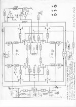
JC-80 balanced input
Earlier in the thread the topic balanced input was briefly touched, without any other conclusion that Jim's PCB although prepared for balanced input was not really suited. I am aware of the fact that the 411 servo opamp fingers the negative input. The JC-80 could possibly has performed as a nice clean balanced in/balance out preamplifier without the actual DC servo regime. It would have required a very precise (four-gang) volume attenuator of course.
The reason for bringing this up [again] is all these nice DAC boxes with balanced outputs.
One could maybe buffer the negative input with a complementary JFET follower - ML-2/"Beast with a Thousand JFETs"-concept.
John Curls old drawing (by Peter Madnick) for reference:
Attachments
You don't need an impossible to buy 0.1% matched 4 gang potentiometer.
Read Bruno Putzeys' article (it's linked a few times in this Forum) on balanced volume control.
It converts the balanced impedance signal to unbalanced, applies the normal stereo vol pot and then converts back to balanced impedance output.
Read Bruno Putzeys' article (it's linked a few times in this Forum) on balanced volume control.
It converts the balanced impedance signal to unbalanced, applies the normal stereo vol pot and then converts back to balanced impedance output.
Yes, AndrewT, thank you for steering me back on a sensible route. I got a little lost here, and also forgot Albert Einstein who said "Make things as simple as possible, but no simpler".
Four-gang potentiometers will not be good enough, and ditto stepped attenuators is to expensive etc (in my opinion). I forgot that, I must admit.
In my opinion a good balanced system must have proper instrumentation amplifiers on the inputs. One should not just route the positive and negative signals through (four-gang) potentiometers and separate amplifier stages. But fully implementing an instrumentation amplifier violates the simplicity of the original design - that is where I got lost last night.
I will check out the Bruno Putzeys article - thanks a lot.
Bruno Putzey article
Here it is and it is well worth reading: http://www.hypex.nl/docs/papers/The G Word.pdf
He also have 7812/7912 compatible regulators: http://www.hypex.nl/docs/HXR12_Short.pdf
Interesting.
You don't need an impossible to buy 0.1% matched 4 gang potentiometer.
Read Bruno Putzeys' article (it's linked a few times in this Forum) on balanced volume control.
It converts the balanced impedance signal to unbalanced, applies the normal stereo vol pot and then converts back to balanced impedance output.
Here it is and it is well worth reading: http://www.hypex.nl/docs/papers/The G Word.pdf
He also have 7812/7912 compatible regulators: http://www.hypex.nl/docs/HXR12_Short.pdf
Interesting.
Hello!
I've got a pair of this new version of the JC-80 from Jim's Audio and I'm going to build it. At first I was also surprised by the location of the IFRs without heatsinks, as there was on the old pcbs, and I asked Stanton (Jim's Audio) directly about this:
"In the old version of this JC-80 pcbs there are place for the heatsinks but in this new version it looks like the IRFs don't need heatsinks and they must be placed over the pcb. Is it correct?"
Then, he answer:
"That's true. The preamp really do not dissipate a lot of heat. so it can be mounted on the board with a small TO-220 heatsink"
However, I keep wondering if this is safe or probably I'll need some bigger dissipation.
Regards,
Ignacio
Also, with this new pcbs, a +-30V PSU is needed. Then, there are a first stage regulation to +-24V for the gain stage and a second stage regulation to +-15V for the servo. I wonder if it would not be better two separate PSUs directly connected to the corresponding pins in the pcb.
Ignacio
Ignacio
Hi Ignacio,
My preamp runs really hot. There is no way a new version would dissipate less without moving away from the design goals (and the sound). Jim is quite nice and friendly, but I assume he did not check with his staff about this.
I have the new boards as well, to build a new incarnation of the circuit, but had no time yet to start it.
One option here is to mount the MOSFETs on the bottom aluminium plate of the box and only use the holes to allow the screwdriver (or TORX driver) to them. This is definitely what I will do, when the time will come, so that the case will become a dissipation element for the heat, so probably that will be better (instead of having a heat source right on the PCB). The drawback is that it will be more difficult to change the parts in case of failure.
Regarding regulators, the first stage is a cap multiplier. The second stage only limits the voltage to supply the op amps, so I would not get into extra PSU complication. I don't think this would bring any benefits...
You need a good PSU for the modules; I use the Kubota power supply, one for each channel, purchased also from Jim. He uses high quality components in the kit (including current regulating diodes) so it is a good investment in my opinion.
i hope this helps you in making the design decisions.
Cheers!
Hi Metallicus,
Thank you for your so much quick reply!. Yes, I think the same. Placing the mosfets on the box will be the best, but that isn't as confortable as mount it in a TO-220 heatsink.
For the PSU, I've never used the Kubota PSU. I'll think about a try, but I have got a pair of sigma22 pcbs unused and I've thought that will probably fit well into this project. What do you think about?.
I've just looking at the photos of your JC-80. A funny thing is that I have the same case!. What pcbs are you using?. I see four red caps that I suppose are the cap multiplier output. I can't see if these are 10 or 0.10uF but I suppose that these must be 0.10uF. Then, aren't you place the electrolitic caps with the .47uF bypass cap?
Cheers!
You are most welcome!
If you have the same case, it will be a bit more complicated, as the bottom is iron, not aluminium. So the dissipation is not that great with that. The new PCBs work best for a full aluminium case.
With the first version (which is used in my build) there is no problem, as I have set the preamp PCBs with the TO-220 heatsinks just under the holes. And it is quite hot! If I were you (as I see you are located in Spain, with an average temperature significantly higher than here in Netherlands) I would give a special attention to this detail.
Kubota was just an indication coming from personal experience. I heard that AMB products are also great, just never had the chance to work with. Probably a good choice.
The caps I used are 10uF and I have 0,47uF under the board. I found it to sound/work just fine like that.
Hi ivigueras,
I last played with this preamplifier a couple years ago and it really is a very nice preamplifier. The voltage stages are the same with the old and new PCBs. +/-30Vdc supply then +/-24Vdc and +/-15Vdc as stated above. It does dissipate quite a bit as metallicus69 stated, that is if you run it at higher bias like it should be. The goal is to stay in class A and as possible in more linear region of the Mosfets. I'm using 2SK2013/J313 instead of the IRF.
Mine are using AMB Sigma22 which are really quiet supplies.
Good luck with your build!
Do
Hi Dominic!
Thank for your advice. I've been reading your contribution in this thread but, until now, not in detail. Did you need to change some resistors values with the 2SK2013/J313?
(I was about to buy your AMB a20 modules a year ago, but someone was faster than me...") ).
).
Ignacio.
Thank for your advice. I've been reading your contribution in this thread but, until now, not in detail. Did you need to change some resistors values with the 2SK2013/J313?
(I was about to buy your AMB a20 modules a year ago, but someone was faster than me...
).Ignacio.
For the 2SK2013/J313 I didn't have to change any resistors but I had to crank the pot much higher for the Mosfet to start conducting but they did.
Talking about the pot, I've seen that recomended pot is about 10K, but I have the 20K Alps RK27. I guess these will work fine too.
Also, thinking about replacing some resistors for some better, like Shinkohs or Z-foil, I've seen that you have replaced some. Looking to the schematics I believe that the more important resistor in the signal path would be 11, 14, 17, 18, 19 and 20. Did you replaced some resistor in the servo?
Cheers,
Ignacio.
- Status
- This old topic is closed. If you want to reopen this topic, contact a moderator using the "Report Post" button.
- Home
- Source & Line
- Analog Line Level
- JC-80 eBay PCBs & Power Train