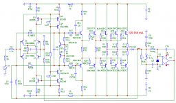
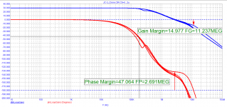
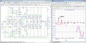
based on the structure of JC-3, made an amplifier model in class AB. First pole about 200 kHz, loop gain in the entire soundband 30 dB, quiescent current of the output transistors 160 mA
Attachments
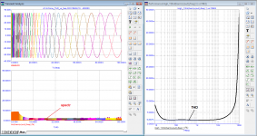
The spectrum is falling.
Unlike amplifiers with a low first pole and in which the increase in distortion starts from 1 ... 2 kHz in this amplifier, the increase in distortion begins above the audio range.
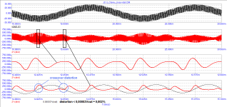
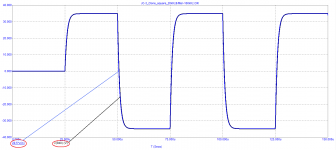
The slew rate of the output voltage is 200 V / μs.
The graph shows a 20 kHz square wave passed through a 160 kHz filter. As you can see, the output signal (black) and the input signal (blue) reduced to the output level by multiplying by Ku practically merge.
Unlike amplifiers with a low first pole and in which the increase in distortion starts from 1 ... 2 kHz in this amplifier, the increase in distortion begins above the audio range.
The slew rate of the output voltage is 200 V / μs.
The graph shows a 20 kHz square wave passed through a 160 kHz filter. As you can see, the output signal (black) and the input signal (blue) reduced to the output level by multiplying by Ku practically merge.
Attachments
based on the structure of JC-3
First one.
You can make a brilliant shine Peter's Baxandall cascode at a given transistor quantity. This will compensate base current leak and increase VAS stage linearity.
Second one.
OPS stabilizing capacitance (as braking one) are better to be placed at second stage B-C junction.


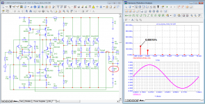
What is the 0.0018% referring to ?
+/-30V output into 8R resistive, 1kHz ?
What would be it like at 1W (+/-4V) into 8R ?
The original JC-3 is Class A, correct ?
Patrick
Patrick, read the charts carefully, they are all signed, the axes are also marked.
At your request, I spread the spectrum of distortions of a 1 kHz signal at an output power of 1 W into a load of 8 ohms
BesPav, what prevents you from posting the test results of your proposals?
Attachments
Last edited:
BesPav, what prevents you from posting the test results of your proposals?
Lazyness and strong understanding how it should be made for reliable performance.
у тебя слишком высокое САМОМНЕНИЕ, гордыня через край, скромнее надо бытьLazyness and strong understanding how it should be made for reliable performance.
Patrick, this is of course a virtual model. It looks like you are not familiar with the simulator, since you do not understand what is reflected in the graphs and its axes
у тебя слишком высокое САМОМНЕНИЕ, гордыня через край, скромнее надо быть
Do not envy.
Just do what i say.
1. How Q4 and Q7 base current are compensated? No way? It's a source of distortion, not so high, but easily measurable.
Being an ingineer you know how and where this current must be returned to be taken into account.
2. EF3 without special attention are inherently unstable, it was discussed so often and so long ago that even the calluses on the fingers have healed. You need to built and burn something from your simulated designs, maybe then you would become think before simulate something.
Despite this i agree, first pole are better to be placed as high as possible with moderate feedback depth through audioband, at an order of ~60 dB.
So why not just use FETs ?
Hi, Patrick!
Good question.
Let's talk how better use brilliant shine of the four-quadrant self-biased JFET input stage.
I'ld build something like attached.
Attachments
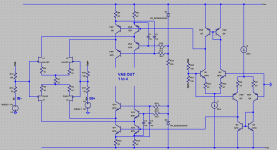
These days, I use non-inverting for convenience, (using servo offset control, instead of an input coupling cap). I usually cascode on the input quad devices to maximize signal swing, buffer the input stage from the power supply, and reduce common mode distortion. I use either power fets or power transistors depending on the amp for the output. Parts quality and layout is all important as well.
Hi, Patrick!
Good question.
Let's talk how better use brilliant shine of the four-quadrant self-biased JFET input stage.
I'ld build something like attached.
Finally build a complete amplifier circuit and present the test results. Or are you afraid that it will burn?
Finally build a complete amplifier circuit and present the test results. Or are you afraid that it will burn?
No, Alexander, i'm afraid that you will burn it.
")
- Home
- Amplifiers
- Solid State
- JC-3 class-a power amp