
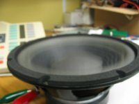
and that poor litle subwoofer...
yes, it does wooof, at 35hz...
cant wait to build a board and the better mosfets...
I will do a full schematic upgrade, with all the component needed to make it work, and the gerbers for the PCB when it will be done.
I will do it a la zappulse i think...
cheers !!!
yes, it does wooof, at 35hz...
cant wait to build a board and the better mosfets...
I will do a full schematic upgrade, with all the component needed to make it work, and the gerbers for the PCB when it will be done.
I will do it a la zappulse i think...
cheers !!!
Attachments
Good stuff.
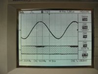
Looks like there's some high frequency ripple/oscillation on your square wave, the gate turn on resistors are pretty small though, could be the cause of that??
It would be really cool to see a before and after of that with the new mosfets when you get them, I dont' think you'll have to wait very long for those either btw.
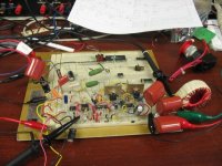
I see you do have some means to cool the mosfets after all (better than nothing).
There probably isn't much point trying to tune it more than it already is on the breadboard, alot will change once you get it on PCB.
It would be cool of you if you took more pictures of how it worked when on the new PCB, and then again with the new mosfets.
You might find your biggest problem is keeping those new mosfets turned off when they're supposed to be, try to keep all the current loops from the driver to the fet as short as possible, ground the drivers right on the source pin if you can.
Thanks
Looks like there's some high frequency ripple/oscillation on your square wave, the gate turn on resistors are pretty small though, could be the cause of that??
It would be really cool to see a before and after of that with the new mosfets when you get them, I dont' think you'll have to wait very long for those either btw.
I see you do have some means to cool the mosfets after all (better than nothing).
There probably isn't much point trying to tune it more than it already is on the breadboard, alot will change once you get it on PCB.
It would be cool of you if you took more pictures of how it worked when on the new PCB, and then again with the new mosfets.
You might find your biggest problem is keeping those new mosfets turned off when they're supposed to be, try to keep all the current loops from the driver to the fet as short as possible, ground the drivers right on the source pin if you can.
Thanks
Hi Pat,
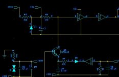
If you wire the bootstrap exactly as you've drawn it in your first "reverse" schematic I think it would work fine.
The bootstrap circuit will only charge the cap when the amp switches low, so check and see if your SD circuit allows the cap to precharge before the output stage is enabled, if it does it should work fine.
I hated this sub that JBL put out. I am a JBL service center, and this amplifier module has been nothing but a headache. Why would JBL not use a Crown (also a Harman International company) design in their powered speakers? The amps that were in these PB12's had more problems than just the amp module going dead. I've seen C6 explode several times, taking out the transformer and all surrounding circuitry with it. I've also seen traces lift off of the PC board near the output resistors. This same design and amplifier module was also used in several Infinity subwoofers. The jacks have failed, the PCB's have poor soldering jobs, etc...... Why can't JBL just make good quality products like they used to? IMHO, they are ruining their reputation as a quality loudspeaker manufacturer with these sub-par products that they keep putting out.
Cheers,
Zach
Cheers,
Zach
Well, the sd thing dont change a thing...thats it, it just feels like it is a shut down where it whould stop to make it oscillate, duno.
the free oscillation is very sensitive, if i modulate a litle bit too much on the input, in stops to oscillate and goes -vcc or a crazy 1khz +vcc, -vcc.
This is with the bootstrap as it should...the best it worked it was when i force feed to upper shmit trigger...
what a piece of ****.
I think my op amp is bad, at least, it is the op amp that was in the module
Lets asume that it is bad.
Hi Zach,
I think I can take a pretty good guess why...
Look at the circuit! Total build cost (mass produced).. I'm not sure.. less than a dollar???
The PSU caps exploding.... because they pinched more pennies and sized them too small.. Obviously, quality is not a concern for them. Just think, someone probably got a big fat check for recommending this topology with respect to every penny they pinched.
Kept you busy though, didn't it? I only hope this screw up cost them far more than it made them! I noticed your key words "that they keep putting out" ...
pat allen said:Well, the sd thing dont change a thing...thats it, it just feels like it is a shut down where it whould stop to make it oscillate, duno.
the free oscillation is very sensitive, if i modulate a litle bit too much on the input, in stops to oscillate and goes -vcc or a crazy 1khz +vcc, -vcc.
This is with the bootstrap as it should...the best it worked it was when i force feed to upper shmit trigger...
what a piece of ****.
I think my op amp is bad, at least, it is the op amp that was in the module
Lets asume that it is bad.
Yeah looking at it again I dont' think the SD circuit is capable of doing anything in that respect. There must be some associated circuitry on the other schematic to help this function, I am unable to follow it though.
Simple cure.
1. Add something like a 1k resistor + diode from +95 rail to the top of the bootstrap cap. You can use a zener there a bit smaller in value than your Vcc supply which sits on the negative rail uses, this way I think it will be disabled while operational, which is good.
2. Add another resistor from the ground side of the bootstrap cap (tried between the mosfets) and tie it to the negative power rail.
Should be pretty high in value, 50K?
You can get it working without the extra zener too, but it will always be taking some charge so use a big enough resistor, and just give it enough of a delay at turn on to allow it to fully charge.
See what that does for ya.
usekgb said:I hated this sub that JBL put out. I am a JBL service center, and this amplifier module has been nothing but a headache. Why would JBL not use a Crown (also a Harman International company) design in their powered speakers? The amps that were in these PB12's had more problems than just the amp module going dead. I've seen C6 explode several times, taking out the transformer and all surrounding circuitry with it. I've also seen traces lift off of the PC board near the output resistors. This same design and amplifier module was also used in several Infinity subwoofers. The jacks have failed, the PCB's have poor soldering jobs, etc...... Why can't JBL just make good quality products like they used to? IMHO, they are ruining their reputation as a quality loudspeaker manufacturer with these sub-par products that they keep putting out.
Cheers,
Zach
Hi Zach, since you are a JBL service center (still?), you might have some good connection with the company?
What i am looking for is the original schematic of the S64AMI module, because i cant figure some components values in mine.
If you cant, do you have someone that i can reach and ask.
Thanks.
BTW, i melted everything.

It never worked as it should, the best i did get is with a lot of tweaks, and it was not that much good.

Hi, what do you think of using half the S64AMI (op amp inputs and comparator right thru the first Schmitt trigger) with the half bridge driver of the previous schematic?
May as well continue this here..
Did you make the PCB for it? I wouldn't expect it to be anything close to good until it's on a PCB, and you'll have to re-tweak it once it is, what you do on the protoboard is just good for a starting point. You can probably measure the value of the caps with a cheap multi meter right?
How come you cant' start it? Still having bootstrap problems?
While you're still fighting with this aspect of it I wouldnt' be so quick to make any radical changes to the design, but you can use a gate driver IC with it of course. Would it be simpler? You'll need at least another power supply, your old SD circuitry will be useless.
Also, while you can use a gate driver, I really wouldn't implement it as per that posted schematic, and it wont' simplify anything, you'll need extra support circuitry and an additional power supply for it, you'll gain the advantage of not needing logic level mosfets.
I believe they used those extra transistors simply to increase drive current, shouldn't be required, use a better mosfet, another reason behind that, they may have been trying to combat the crappy rise time of the IC, but it also say's it has an internal deadtime .... ~650ns!!! I wouldn't use that chip either.
Regards
Tekko said:I´m impressed of your work, Pat
Thank you, hi havent done anything that much incredible, maybe just opening the AMI module is something...
classd4sure : why do you say that i will have to redo the power supply if i want to use the IR2111?
-because of the high voltage rail and low current?
-because of the new requirement of a +15vdc referenced to the -vcc?
it already have a +15, 0,-15 for the op amp, and for the +15vdc referenced to the -vdc, there is already a +6vdc referenced to -vcc, all it needs is to change the zener value, this voltage was used on the AMI for the bootstrap, same thing with the IR2111.
The digital mosfets you suggested me are NA for now, at all our distributors, and even directly at Fairchild
I plan to order few of thoses Ir2111 anyway, and play with them.
thanks.
Hi, there seems to be a lot of IR driver from international rectifiers, i have looked at the IR2104, it have a shut down circuit where it shut off both outputs, could be good for the subwoofer application where when it is not used (waiting for music to get in), it could be not oscilating then no possibilities of burning it??
And what about the self oscillating ones?
One could modulate the frequency on its input and might get some sort of ultra cheap D amp???
I will order all of them and play
And what about the self oscillating ones?
One could modulate the frequency on its input and might get some sort of ultra cheap D amp???
I will order all of them and play
- Home
- Amplifiers
- Class D
- JBL PB12 subwoofer, Class D amp, dead.