If you had to pull all 4 640s, it probably means there's a problem with the driver transistors. You need to pull them and check them. If you're unsure of the readings, use the form on the basic repair page and send me the screen caps of the readings from each transistor.
If you haven't done so already, check the 10 ohm resistors connected to the gates of the 640s and 9640s.
You should also check the solder connections on the 9640s and the driver transistors to confirm that there are no solder bridges.
Check the newly replaced 9640s also. If one failed for some reason, that could cause the 640s to overheat.
Power semiconductors can only perform to spec when clamped to the heatsink. The transistor may be rated for 150 watts but can only survive a few watts when off of the heatsink. When there is a fault causing high power dissipation, the transistor can overheat and fail within seconds if it's not clamped to the sink. When it's tightly clamped to the sink, the increase in temperature is less significant so it takes longer for the transistor to fail.
Is the board burned before you begin soldering or does it burn during the soldering/desoldering process?
Many times, the power supply FETs will burn the board. When it does and the board becomes conductive. The sparks are produced when the conductive areas of the board burn. You have to chip away all of the carbonized material until you get back to clean fiberglass. If you don't, it may begin to burn again (which can leave a large hole in the board - making the amp unrepairable).
After chipping away all of the bad material, you need to clean the area with solvent (acetone - read instructions and use it outside). After letting the solvent evaporate, you'll check the resistance in the fiberglass around the damaged area. With the meter set to ohms and the probes as close as possible, probe the fiberglass around the perimeter of the damaged area. The meter should never read anything other than infinity (open) unless you accidentally let the probes touch. If you read anything other than infinity, you have to chip away more of the board.
so if i did cook the irf9460s and the driver transistors are ok. what gives? what else would cause all 6 of the fets to fry?
right now with i have (on one side only) all the irf640 irf 9640 pulled and also the driver transistors pulled and it seems to be powering up nicely. the 12v light in the center shines bright and nothing is dragging down the supply voltage.
my iron is hot and waiting to yank out more parts. if need be i found a second one of these amps and it should be arriving shortly. its been helpful while im learning to buy broken amps in pairs. its sorta costly but handy as a referance. let me know if you want me to wait till the 2nd one gets here to check stuff on that
i have bought 3 different meters and i have a 4th (fluke) on the way, the readings im getting from the 3 different meters i have here are all simalar and all sorta weird.
the IRF9640 i have 6 of these in total (on one side) and i replaced all of them with ones from MCM and im getting 1200-1350 on diode check with the leads like #5. i pulled one from the other side and i found the measuring with probes like on image #5 i got 250. but if i put the probes in different configurations then they seem to act like opening doors and closing doors just like the BCAE1 website says. i cant get the other "new" IRF9640s to do replicate this
i put up a picture of the FET that i suspect is good i can get it to read 250 but if i start moving the meter around and open and closing the transistor then the same #5 test jumps from 250 to 865.
from what i have read it should be around .6 im wondering if 250 is .25
im still a little unclear how to test these things. but im reading the BCAE1 website as much as possible
Attachments
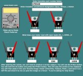
On page 97, read the section labeled Checking Field Effect Transistors.
You have to perform the tests in the proper order. If you go out of order, you must start over. The test shows the procedure for an N-channel FET. Reverse the leads in your meter to test the P-channel IRF9640.
The P-channel may read as high as ~0.800 where the graphic shows a reading of 0.445.
Don't forget to switch your meter leads back when you finish testing.
If the new (unused) FETs don't read something close to what you read on the one you pulled from the good side, they may be defective.
i have tested the pulled 9640s a 9640 from the other side and a brand new 9640 from a local supplier.
i found 3 of 6 from mcm to be NFG. if i follow the test on page 97 with the leads reversed and i get all "open" readings.
the other 3 seem to pass and i get .96 and 2x .98. on the last test with the red on the right and the black in the center.
the one from the other side of the board measured at .755
the completely new unused one from local store measures at .85
i seem to be getting pretty different results from most all of them. is it normal to get defective ones? is it a common practice to test before putting them in? what test should i use to check the IRF640S are these just normal N-channel FETs? or should i keep the leads revesed? and what number should i be looking for when testing them?
0.9+ is high. The ones reading 0.85 and lower are probably OK (especially if they read as open when checking from 1-2 on ohms).
I've purchased tens of thousands of FETs and have only had a handful (probably less than 20) defective. I generally buy from Mouser, Digi-key or FAI (componentssuperstore.com). I purchased some IRFZ46s from MCM because someone thought they got a bad batch and they did. It's VERY rare that you get defective parts. I'm going to order some of the 640s and 9640s from MCM to see if they are defective. If they are, I'll report it to the manufacturer and MCM like I did for the Z46s. If I find that the 640s and 9640s from MCM are defective, I'll no longer recommend them as a source for FETs.
Insert the meter leads normally and test as shown on the site. These will read similarly to the 9640s but the last test numbers will probably be significantly lower (closer to 0.45 than to 0.85).
No. I need to buy them myself. That way I can say, with confidence, that they came from MCM. Otherwise, they could claim that someone mixed them with those from another supplier. I'll also be able to unpack them under controlled conditions and test them with no question that they may have been subjected to static discharge.
If you live in an area where static discharge is a problem, you should be working with a wrist/ankle strap to drain any static charge from your body. I don't use a strap and have never damaged an FET but it's good practice to wear one (especially if you live in a cold, dry environment).
As a side note, don't ground yourself directly (i.e. jumper wire from watchband to ground terminal of power supply). Ground straps have 1 meg-ohm resistors connected in series between the ends of the strap to prevent electrocution.
HI Perry, I've been attempting this repair. I have blown 4 power mosfets (IRF3205), so I just replaced the entire rail. Then when I tested them, the relay clicks,the 3205 rail I replaced got hot and the light dimmed,lucky I tested it with a small PSU or it would of burnt out. Since I had extra 3205s, I just replaced them all, and now the relay does not click and it stays in Protect mode, I'm assuming theirs still a problem in the power supply. Any advice??
How do you define 'entire rail'?
Whenever you power up the amp, you should have all of the transistors clamped tightly to the heatsink. This will help protect them. You should also have a 10-15 amp fuse in the B+ line feeding the amp.
Post the DC voltage on the pins of the TL494. If you don't know the pin configuration/numbering, Google:
TL494 datasheet
I've replaced this chip also, I forgot to mention,but it was still giving me the same effects.
The pin out Readings are
1:3.78V
2:5.01V
3:4.78V
4:5.31V
5:1.47V
6:3.7V
7:2.6mV
8:11.26V
9:2.5mV
10:2.6mV
11:11.26V
12:11.26V
13:5.01V
14:5.01V
15:5.01V
16:728mV
Whenever I touch Pin 16 with anything conductive,or when ever I put the test probe on it,it makes a small pop noise,and the light dims greatly,maybe because its ground ???
I've attached a schematic readout of what the pins should be,and some look way off,especially Pin 4,9,10.
I diode checked the 1266 transistors and they checked good.
I've heard that your Tutorial was worth the money for doing this type of work, I cant wait until I receive my taxes so I can check it out. and the free information you have on sites has helped me tremendously.
Attachments
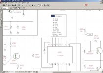
It's in protect but there's something strange about the voltage on the 494. According to the error amp inputs, the voltage on pin 3 should be nearly 0v. According to the schematic, there is nothing connected to pin 3 that could drive it high. I'd suspect a damaged IC but you've already replaced it.
Pin 4 is too high also. Post the DC voltage on the pins of U702.
Pin 4 is too high also. Post the DC voltage on the pins of U702.
1:2.51V
2:6.3mV
3:2.74V
4:3mV
5:4.42V
6:2.83V
7:5V
8:11.26V
I forgot to mention that I've made a mistake while testing the 1266s, it turned out that I replaced one of them with a 3198 instead of the 1266. which is Q703 in the previous attachment picture, which is connected to pin 4,13,14 and 15. I have a feeling that I may have damaged the new IC by exchanging the PNP for a NPN. I've ordered 10 new ICS hopefully they will be here tomorrow or Sat. what do you think?
- Status
- This old topic is closed. If you want to reopen this topic, contact a moderator using the "Report Post" button.
- Home
- General Interest
- Car Audio
- Jbl Bp1200