On my UcD180 modules I bought 2 months ago are mounted the STP14NF10FP:
http://www.st.com/stonline/products/literature/ds/7779/stp14nf10.pdf
Cheers")
http://www.st.com/stonline/products/literature/ds/7779/stp14nf10.pdf
Cheers
Hi, Chris,
I noticed something. I made alot of power amps that uses +/-45V rail supply, all conventional (not classD).
I haven't measure anything, nor measure under load through osciloscope, but why I get a feeling that UCD180 with +/-45V rail supply seems cannot get the same impact/powerfull as conventional (classAB) power amp under the same rail?
I remember this is quite like Quad405 amp (current dumping). It also uses inductor on the output, and this one too seems to have less impact/powerfull under the same rail voltage.
Is this typical of power amps that rely on inductors as main peripheral on the output stage?
PS : Is the output inductor on UCD180 is not too small (in physical dimension, not in uH henry value)? It is very small
No I don't think it is typical of an amp with an inductor in the output, especially not so in the case of this one since feedback is taken after that inductor.
You're hearing an ultra clean and very controlled type of bass though, which most amps dont' have. So it's very different already, too pure some think.
Additionaly there are the other reasons I discussed with you in email.. and I believe those to the main ones. Try the recommendation I gave you and we'll see what you think about the power then.
classd4sure said:
Yes, it seems there is the same die in it but according to the datasheet these devices are 100% avalanche tested. If they will all pass the 120V test there will be no separate 100V version.
So, if there are STP14NF12FP’s on you’re module you are lucky. If there are STP14NF10FP’s on it I would stay on the safe side. However if you look at R_DS(on) of both devices it differs, so I doubt it is exactly the same die.
Cheers
Hi,
The process probably went through some minor changes /improvements. You'd be very hard pressed to find the 100V version available anymore, so I think it got phased out in place of the 120.
If Hypex rated the module as they have, it can only be because it was discussed with ST and they got the thumbs up to do so safely. Anything less than that would simply be absurd, because the mosfets would blow before overvoltage kicks in. I also have the 100V mosfets in my version 4.
Since you have a few spare modules, why not try it at 52V rails and see? Personally I'm not that curious, but I think it would take it. There's also not very many who reported blown mosfets due to using rails that push the upper limits, I think that say's alot.
BTW I agree with your method of course, one needs a designed margin without question. However a good engineer also takes advantage of circumstances whenever possible, and it seems like this is the case here. If you have some insider information and these guys often do, you can get away with that sort of thing nicely. As for us suckers who are stuck reading data sheets only... best to go for a safe margin.
Cheers,
Chris
The process probably went through some minor changes /improvements. You'd be very hard pressed to find the 100V version available anymore, so I think it got phased out in place of the 120.
If Hypex rated the module as they have, it can only be because it was discussed with ST and they got the thumbs up to do so safely. Anything less than that would simply be absurd, because the mosfets would blow before overvoltage kicks in. I also have the 100V mosfets in my version 4.
Since you have a few spare modules, why not try it at 52V rails and see?
Personally I'm not that curious, but I think it would take it. There's also not very many who reported blown mosfets due to using rails that push the upper limits, I think that say's alot.BTW I agree with your method of course, one needs a designed margin without question. However a good engineer also takes advantage of circumstances whenever possible, and it seems like this is the case here. If you have some insider information and these guys often do, you can get away with that sort of thing nicely. As for us suckers who are stuck reading data sheets only... best to go for a safe margin.
Cheers,
Chris
Hi, Chris,
Yes, thanks for those advice When I have tested them I will tell you, but seems not in these days.
I have a tought of that too. I think the sense of "impact" is actually a mix of music signal and distortions of the power amp.
I have heard amps that has 0.00....THD number, and the sound doesn't seems right to my ears Maybe it is the right one technically, but too clean. It is good for hearing music (or hearing tweeter/loudspeaker components, and not hearing the music itself? ) when we are under stress and full concentration as in a judge in a courtroom .
But for hearing music for feeling good or relax or enjoyment, amps with some distortions (to a certain degree) suits better
Yes, thanks for those advice
When I have tested them I will tell you, but seems not in these days. You're hearing an ultra clean and very controlled type of bass though
I have a tought of that too. I think the sense of "impact" is actually a mix of music signal and distortions of the power amp.
I have heard amps that has 0.00....THD number, and the sound doesn't seems right to my ears
Maybe it is the right one technically, but too clean. It is good for hearing music (or hearing tweeter/loudspeaker components, and not hearing the music itself? ) when we are under stress and full concentration as in a judge in a courtroom . But for hearing music for feeling good or relax or enjoyment, amps with some distortions (to a certain degree) suits better
Yeah,
It's a very subjective thing at this point. It can be too analytic, dry, not musical enough. I think it's possible to achieve a technically pure sound and still have it musical though.
It does take a bit of getting used to the clean bass as well, because it's very different from what we've come to know. Once you try that little mod and bring a little power out of it in the low end, where you can feel it more and at lower frequencies, you'll see that it's still clean and very pleasing/fun.
PS: IVX has mentioned this before, putting a small resistor in series with the output to dampen the damping ratio, muddy up the bass a little, so people would enjoy it more. Said they're just not ready for such a clean sound.
Pjotr said:
Yes, it seems there is the same die in it but according to the datasheet these devices are 100% avalanche tested. If they will all pass the 120V test there will be no separate 100V version.
So, if there are STP14NF12FP’s on you’re module you are lucky. If there are STP14NF10FP’s on it I would stay on the safe side. However if you look at R_DS(on) of both devices it differs, so I doubt it is exactly the same die.
Cheers
Agian, it's the same die....
All STP FETs what we have used in the UcD180 are rated for 120V.
Don't forget that in reality the product could be better as written in the datasheet....
Jan-Peter
Hi Jan-Peter,
The same die does not guarantee the same avalanche voltage. The datasheet does NOT guarantee an avalanche voltage of 120V. So if you guarantee all SNP14FN10FP fets you use are safe at 120V it can only so if you (or the manufacturer) tests ALL fets for avalanche breakdown before using or by testing at the end control at a rail voltage at plus and minus 60V for an extended period.
Please can you confirm you are doing so?
Cheers
Pjotr said:Hi Jan-Peter,
The same die does not guarantee the same avalanche voltage. The datasheet does NOT guarantee an avalanche voltage of 120V. So if you guarantee all SNP14FN10FP fets you use are safe at 120V it can only so if you (or the manufacturer) tests ALL fets for avalanche breakdown before using or by testing at the end control at a rail voltage at plus and minus 60V for an extended period.
Please can you confirm you are doing so?
Cheers
It's exactly the same FET only the printing is different, if you don't believe me it's fine for me....
Hi Jan-Peter,
Its not a question of believing, it is a question of knowing. In other words, I was only asking if you can guarantee the UcD180’s will not be damaged by using them at higher voltage than the absolute maximum rating as stated in the data sheet.
If you can not guarantee that, it is not fair to point people in that direction risking damage or other unreliable behaviour. In fact that is my only point.
So, if it is not wise to use them at rail voltages above 50V, the whole question of the fet’s break down voltage is pointless.
Pjotr said:Hi Jan-Peter,
Its not a question of believing, it is a question of knowing. In other words, I was only asking if you can guarantee the UcD180’s will not be damaged by using them at higher voltage than the absolute maximum rating as stated in the data sheet.
If you can not guarantee that, it is not fair to point people in that direction risking damage or other unreliable behaviour. In fact that is my only point.
So, if it is not wise to use them at rail voltages above 50V, the whole question of the fet’s break down voltage is pointless.
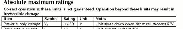
Strange discussion......(and the UcD180 stops working above 52VDC...)
The FETs of the UcD180 will not be damaged by a higher voltage as 2x50VDC. We know that ST uses the same FET for the STP14NF10 and STP14NF12 version.
We hardly have problems with FETs broking down because of too high voltages. Some customers did use preamps with a very high switch ON/OFF DC offset voltages. This did create a short power supply pumping effect, and the power voltage increased so much that the small 22uF decoupling capacitor exploded. But in the most cases the FETs were not broken......
I will not guarantuee anything but only tell our experience and what we know about the difference between the STP14NF10 and 12.
Everybody is free to draw his own conclusion.
Jan-Peter said:
We know that ST uses the same FET for the STP14NF10 and STP14NF12 version.
As far as I can conclude from your writing is that there is the same chip in it. But that does not mean that both chips are rated for 120V avalanche or can stand 120V, only the 12’s did pass the 120V test.
If it is the same chip then it is very likely that the chips that pass the 120V test become the 12’s and chips that fail the 120 V test but pass the 100V test become the 10’s. This is business as usual for chipmakers.
The story s different, the 100V FETs could stand an higher voltage (120V). But ST didn't want to remove the 100V version from the market because certain companies did designed the 100V version in their product. So they decided to put a 120V version in the market....
Now the 100V version is obsolete, and only the 120V version is available.
That's the story nothing more.....
Jan-Peter
Now the 100V version is obsolete, and only the 120V version is available.
That's the story nothing more.....
Jan-Peter
Ok, thanks JP,
But we could have save us above discussion if you gave us that information 10 posts earlier.
Now the fet devices can stand 120V, are you planning to redimension the OVP to take advantage of it? Or are there other factors prohibiting that?
Would be nice because I have a box full of old 220V/32V toroides around that will give slightly over 50V at idling at the now 230V mains voltage. If the OVP trips at higher voltage I don’t need to unwind some secondary turns.
Cheers
- Status
- This old topic is closed. If you want to reopen this topic, contact a moderator using the "Report Post" button.
- Home
- Amplifiers
- Class D
- Jan Peter help