agreed. But filter caps may be the same physical size, more uf of less volts. Half the rail volts but twice the current. Equal current from each rail leads to better CM operation. Higher conductance devices are required but the lower voltage one do seem to be cheaper, at least for Mos. Also a bridge amp can work from a single rail without an output cap.
agreed. But filter caps may be the same physical size, more uf of less volts. Half the rail volts but twice the current. Equal current from each rail leads to better CM operation. Higher conductance devices are required but the lower voltage one do seem to be cheaper, at least for Mos. Also a bridge amp can work from a single rail without an output cap.
Yeah, correct.
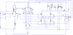
Btw: my latest Grounded bridge with floating rails and monorail switch.
Attachments
Mosfet, may be later, I am going to make simple driver for its tracking rail first") .
.
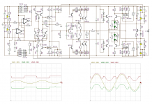
That looks like Class AH.
Ok.
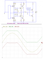
Here are two attachement.
First, only linear applied:
1. Half power required for classA operation.
2. Lower (half) components voltage rating. The current rating will be the same.
3. Simpler power supply.
4. Wider component choice because of 1. and 2.
Second is using switching assistant.
1. Much more.
.That looks like Class AH.
Ok.
Here are two attachement.
First, only linear applied:
1. Half power required for classA operation.
2. Lower (half) components voltage rating. The current rating will be the same.
3. Simpler power supply.
4. Wider component choice because of 1. and 2.
Second is using switching assistant.
1. Much more.
Attachments
Mosfet, may be later, I am going to make simple driver for its tracking rail first
That looks like Class AH.
Ok.
Here are two attachement.
First, only linear applied:
1. Half power required for classA operation.
2. Lower (half) components voltage rating. The current rating will be the same.
3. Simpler power supply.
4. Wider component choice because of 1. and 2.
Second is using switching assistant.
1. Much more.
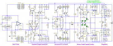
Nice one, show the full schematic at least
Nice one, show the full schematic at least
No, too complex for DIY, it has 100V opamp inside
, (Hehe, beter not to show it) also the schematic is changed. May be it can be simple later, or may be not.Hi, make your ANFET class B and you will find the same result.
Don't worry I am planning to buy plenty(maybe only 100) pair of BD139/140 in this week end, to finish this one.
I have two choice to share and to not share the schematic.
Reason:
*Not to share, because it is one of potential neighbor disturbing amplifier (Kilowatt rated), that I will have its responsibility.
*To share because just you ask. No, Not to share still has stronger reason.
Don't worry I am trying to finish it in another simplest way that able to be shared. It will has plenty BD139/140 (gift from the past), plus watt dissipating devices from any cheapo (TIP2955/3055 or cheap mosfets), plus this winner single supply topoplogy, and may be plus my Br&Br amplifier emulator (VL86). May the result can be greatest one.
Just take a look another first, this is my searcing result (it also has schematic inside) I am starting with google then found many in patent region:
Output transformerless push-pull full bridge power amplifier having floating power supply - Patent 3383613
HIGH POWER BRIDGE AUDIO AMPLIFIER - Patent 3808545
Switch mode - class B power amplifier - Patent 4398159
http://www.crownaudio.com/pdf/amps/grbgpapr.pdf
newer:
Bridge-type linear amplifier with wide dynamic range and high efficiency - Patent 4910477
High fidelity floating bridge amplifier - Patent 6747513
Method and device for improved class BD amplification having single-terminal alternating-rail dual-sampling topology - Patent 6097249
I don't see any patent similar with Mackie's Subwoofer.
I have two choice to share and to not share the schematic.
Reason:
*Not to share, because it is one of potential neighbor disturbing amplifier (Kilowatt rated), that I will have its responsibility.
*To share because just you ask.
No, Not to share still has stronger reason.Don't worry I am trying to finish it in another simplest way that able to be shared. It will has plenty BD139/140 (gift from the past), plus watt dissipating devices from any cheapo (TIP2955/3055 or cheap mosfets), plus this winner single supply topoplogy, and may be plus my Br&Br amplifier emulator (VL86). May the result can be greatest one.
Just take a look another first, this is my searcing result (it also has schematic inside) I am starting with google then found many in patent region:
Output transformerless push-pull full bridge power amplifier having floating power supply - Patent 3383613
HIGH POWER BRIDGE AUDIO AMPLIFIER - Patent 3808545
Switch mode - class B power amplifier - Patent 4398159
http://www.crownaudio.com/pdf/amps/grbgpapr.pdf
newer:
Bridge-type linear amplifier with wide dynamic range and high efficiency - Patent 4910477
High fidelity floating bridge amplifier - Patent 6747513
Method and device for improved class BD amplification having single-terminal alternating-rail dual-sampling topology - Patent 6097249
I don't see any patent similar with Mackie's Subwoofer.
Last edited:
Sorry, the switching assistant is removed for some reasons.
LOL
LOL also appreciated
Seems that BJT power output stage cannot handle the rail ripple in low feedback mode. I am going to migrate it into MOSFET, there are two choices await:
1.Using my quasi, with crossing management, fastest and lowest distortion.
2.Using my simplest floating driver. Only need +/-12Volt floating supplies, low power consumption.
3.There are two choices, anyone if any third choice please suggest.
LOL also appreciated
Seems that BJT power output stage cannot handle the rail ripple in low feedback mode. I am going to migrate it into MOSFET, there are two choices await:
1.Using my quasi, with crossing management, fastest and lowest distortion.
2.Using my simplest floating driver. Only need +/-12Volt floating supplies, low power consumption.
3.There are two choices, anyone if any third choice please suggest.
I wonder how well this would work in class G with an N-ch/P-ch pair and just a simple zener level shift?
Somewhat easy and linear envelope follower
Mackie's topology also added two more mosfets and advantage of using power waste transistor only one series with battery, and not pair at +and-. The only difficulty is to achieve 10KHz and up.
Well and easy for dual supply, with single supply switched, the mosfet capacitance will kick the rail when voltages fast rise and fall. The problem is low error correction output that used here, that the supply must be low ripple, or change it with high error corrected output.
May be it is better to use Mackie's single supply, Mackie win again.
Well and easy for dual supply, with single supply switched, the mosfet capacitance will kick the rail when voltages fast rise and fall. The problem is low error correction output that used here, that the supply must be low ripple, or change it with high error corrected output.
May be it is better to use Mackie's single supply, Mackie win again
."only one series with battery, "
I'm not sure of what you are getting at here, the Mackie has two mosfets in series with the battery, one for the + rail, and one for the - rail.
If Mackie had used an IRF9540 for the -rail switch (instead of an IRF540) they could have just used a TL082 instead of having to build a high voltage opamp with discrete parts.
Last edited:
Yes, only one series with batteries to make its voltage variable. In this case Mackie using switching converter instead of dissipate power. Those mosfet at + and - rail only switch the voltage to ground and not to dissipate power.
I am now planning to mix both Mackie's with this.
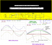
It will start with 20V (regulated from 50V). With center reference it will smoothly track the output until it reach almost 20V (see post#23 only linear applied picture) then the voltage rises to track the output until 50V (in this case the output is almost 50V sine). Then it track down until 20V again.
The regulator here take major power dissipated, and regulator is only one series with battery, right??.
In normal class B amplifier with dual rail, the transistor that in inactive session is not dissipating power and just off.
With this next mixture, we don't have to dissipate power at output transistor, but in regulator. We may choosing high quality output stage for amplifier and cheapo transistor to dissipate power with no inactive session.
I am now planning to mix both Mackie's with this.
It will start with 20V (regulated from 50V). With center reference it will smoothly track the output until it reach almost 20V (see post#23 only linear applied picture) then the voltage rises to track the output until 50V (in this case the output is almost 50V sine). Then it track down until 20V again.
The regulator here take major power dissipated, and regulator is only one series with battery, right??.
In normal class B amplifier with dual rail, the transistor that in inactive session is not dissipating power and just off.
With this next mixture, we don't have to dissipate power at output transistor, but in regulator. We may choosing high quality output stage for amplifier and cheapo transistor to dissipate power with no inactive session.
Yes, only one series with batteries to make its voltage variable. In this case Mackie using switching converter instead of dissipate power. Those mosfet at + and - rail only switch the voltage to ground and not to dissipate power.
I am now planning to mix both Mackie's with this.
It will start with 20V (regulated from 50V). With center reference it will smoothly track the output until it reach almost 20V (see post#23 only linear applied picture) then the voltage rises to track the output until 50V (in this case the output is almost 50V sine). Then it track down until 20V again.
The regulator here take major power dissipated, and regulator is only one series with battery, right??.
In normal class B amplifier with dual rail, the transistor that in inactive session is not dissipating power and just off.
With this next mixture, we don't have to dissipate power at output transistor, but in regulator. We may choosing high quality output stage for amplifier and cheapo transistor to dissipate power with no inactive session.
But i can see a class-A biased output section till +/-20V and class-AC till rest of the swing and step being in class-G linear envelope follower as best for high-end thing.
Yes like that. Class AB for +/-20V then track more until the rest (50V if the supply is 50). Any better solution?
I am buying 40 of BD139/140 this day. They are out of stock. <Rp1000 each for BD(ST), <Rp5000 each for IRF540/9540(IR). $1~Rp10000. Cheap enough when compared to A1943/C5200 at Rp33000 for 1 pair.
I am buying 40 of BD139/140 this day. They are out of stock. <Rp1000 each for BD(ST), <Rp5000 each for IRF540/9540(IR). $1~Rp10000. Cheap enough when compared to A1943/C5200 at Rp33000 for 1 pair.
- Status
- This old topic is closed. If you want to reopen this topic, contact a moderator using the "Report Post" button.
- Home
- Amplifiers
- Solid State
- Its only need +50V for +/-45V outputs.