you can make virtual ground for every device that needs it in your gadget...
guitar pedals use this all the time...
two equal value resistors to serve as half your single rail is sufficient
(1/2 rail guarantees maximum ac output swing if that is what you want)
in most applications. and if you worry about output offset voltages,
then use capacitive coupling between stages is an effective solution...

But now again, going back to the original solution I've been kicking around, do YOU see a problem letting such a small V-Gnd voltage difference just exist across my proposed 50ohms? So far I've seen this difference be in the order of 10mV, which would only cause about 200 uA of unwanted current. I haven't measured any increased noise so far in the bench test, but audibly it all sounds very quiet, even with my test amplifier cranked.
In as far as its goes and I don't foresee any real issue. The static voltage difference between the two grounds isn't an issue... where things fall apart is under dynamic conditions.
Why not test the set up by driving an opamp in each half of the combined circuit to near clipping with say a 1kHz sine. Load that opamp with say 1k5 to its own virtual ground and check that there is zero 1kHz from the second stage. You would have to have the scope ground on the virtual ground of the stage you are actually measuring in order to get a true result.
Look at the LM3886 datasheet, you'll see that in the single-supply version (AC coupled) the negative rail is connected to ground.
Terminology... in a single rail design the phrase negative rail doesn't really mean anything. I know what you mean for that particular reference but its all down to wording and interpretation.
In a dual rail design, whether virtual ground or not, you are ill advised to connect any signal returns to a rail (even if they are AC coupled and even if the rails and ground are nominally the same impedance at AC) simply because if you measure either rail with respect to ground you will see disturbance, whether it be PSU related or due to the dynamic loading of the circuit. Couple to the rails and you feed that disturbance back into the amp.
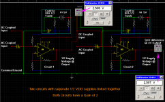
This is how i envisage Peter Pan sees it ? If so the sim doesn't show any problems !
Well I appreciate that work up! The difference in my situation, in a nutshell, is (1) both 5V and 0V supply sources are one and the same, and (2) the 1/2 V points ARE OPA generated, and will get cross connected. See, in your simulation, the DC value of the 1/2V points are simply resistor generated. If you joined any number of such 1/2V points together, any differences would simply amount to some ohms law based network analysis, that would certainly be stable. But replace those 1/2V points with ACTIVE devices, hell bent on maintaining their voltage through negative feedback, and THEN tie them together, there is going to be a fight over any differential. In my experience, such fights rear their heads in AAAs (my techie term for audibly awful aberrations
") . OP amp drive V-Gnds have advantages though, so my solution "described in the first post"
. OP amp drive V-Gnds have advantages though, so my solution "described in the first post"In as far as its goes and I don't foresee any real issue. The static voltage difference between the two grounds isn't an issue... where things fall apart is under dynamic conditions.
Why not test the set up by driving an opamp in each half of the combined circuit to near clipping with say a 1kHz sine. Load that opamp with say 1k5 to its own virtual ground and check that there is zero 1kHz from the second stage. You would have to have the scope ground on the virtual ground of the stage you are actually measuring in order to get a true result.
Thanks Mooly. Yes I have bench tested in a variety of ways. But as you noted, "dynamic" conditions are where things can fall apart, and "dynamic" has often meant "including the case I haven't tested yet.
This has gone long enough without my offering a clear example of my own situation... definitely MY BAD! I'm going to follow up now with a partial diagram.
MY BAD... and apologies all around for all the confusion I have surely caused by not offering a schematic. There were just too many distractions and "black boxes" to post the actual project, but here is a simplified diagram of the critical issue I've been speaking of.
If you'd prefer, just look at it at this link in another browser window...http://pixyland.org/temp/VGND_EXAMPLE.jpg
So the left side of the circuit has a simple unity gain amplifier which can connect to the outside world. The +5 and 0V are generated by a regulator in this "device #1". It is an isolated supply that no one can share, unless its one of MY devices. Note that The signal and signal ground output from device #1 are composed of the output of A1a and the V-Gnd-1 generated by A1b. Now on the right side there is a partial circuit representative of my device #2. It shares the 5V and 0 supply sources (rails, whatever), by virtue of a short (2 foot max) power cable. Like device #1, this device may also accept input from a wide variety of external sources, including my device #1, via a short (again, about 2 foot max) audio coax cable. Since the second device must be able independently usable, it creates its own V-Gnd-2 via A2B, but notice that I've added a 50 ohm resistor, RX, highlighted in RED. The reason is because in the case where the devices are connected via the short audio cable as shown, there is likely to be a small differential between the V-Gnds. As I think we're all agreed at this point, any slight such DC difference should gracefully disperse across that 50 ohm resistor. But as Mooly pointed out, there is the possibility of unforeseen dynamic issue. I've not seen any on the bench, and I have my fingers crossed that the local capacitors at both the inputs and outputs of each V-Gnd (and the fact that the V-Gnds are unity gain), should ensure against any odd stability problems, which I have yet to see or dream up. But my whole reason for posting is because truth is stranger than fiction, and I'm fishing for what could go wrong dynamically, and what I might do about it. Again, assume device #1 (left) is much harder to change at this point than the one at right.
An externally hosted image should be here but it was not working when we last tested it.
If you'd prefer, just look at it at this link in another browser window...http://pixyland.org/temp/VGND_EXAMPLE.jpg
So the left side of the circuit has a simple unity gain amplifier which can connect to the outside world. The +5 and 0V are generated by a regulator in this "device #1". It is an isolated supply that no one can share, unless its one of MY devices. Note that The signal and signal ground output from device #1 are composed of the output of A1a and the V-Gnd-1 generated by A1b. Now on the right side there is a partial circuit representative of my device #2. It shares the 5V and 0 supply sources (rails, whatever), by virtue of a short (2 foot max) power cable. Like device #1, this device may also accept input from a wide variety of external sources, including my device #1, via a short (again, about 2 foot max) audio coax cable. Since the second device must be able independently usable, it creates its own V-Gnd-2 via A2B, but notice that I've added a 50 ohm resistor, RX, highlighted in RED. The reason is because in the case where the devices are connected via the short audio cable as shown, there is likely to be a small differential between the V-Gnds. As I think we're all agreed at this point, any slight such DC difference should gracefully disperse across that 50 ohm resistor. But as Mooly pointed out, there is the possibility of unforeseen dynamic issue. I've not seen any on the bench, and I have my fingers crossed that the local capacitors at both the inputs and outputs of each V-Gnd (and the fact that the V-Gnds are unity gain), should ensure against any odd stability problems, which I have yet to see or dream up. But my whole reason for posting is because truth is stranger than fiction, and I'm fishing for what could go wrong dynamically, and what I might do about it. Again, assume device #1 (left) is much harder to change at this point than the one at right.
Last edited:
There shouldn't be any stability issues. I think that's a non issue.
This would be an interesting exercise to simulate you know. Because the simulation is "perfect" with regard to parts matching you could easily create an imbalance between the virtual grounds (just make one of the 100k's say 99990 ohms).
I'd be interested to know what the output voltage would be when used in DC mode and how any difference in virtual ground voltage would affect the result.
There shouldn't be any stability issues. I think that's a non issue.
This would be an interesting exercise to simulate you know. Because the simulation is "perfect" with regard to parts matching you could easily create an imbalance between the virtual grounds (just make one of the 100k's say 99990 ohms).
I'd be interested to know what the output voltage would be when used in DC mode and how any difference in virtual ground voltage would affect the result.
Well from a DC point of view, AND with parts drawn from the same lot, I've seen my differential be in the neighborhood of 10mV, which I can't account for. But from a simulation point of view, I dunno Mooly... my instinct tells me that by biggest concern is Mr Murphy. meaning, the outside connections to "unknown devices" sending different audio signals (there are lots more ins and outs than my circuit shows), and somehow toggling that magic combination that starts some kind of oscillation or motor-boating between the multiple analog grounds. I guess I'm going to have to hope that by letting potential customers "have at it" with my new "adapter" device, Mr Murphy will rear his ugly head. Unfortunately by that time PCBoards will have been cut. But at least this time I might get away with a 2 layer board, and some judicious ground runs and copper pours. Crossing my fingers!
*My BoldTerminology... in a single rail design the phrase negative rail doesn't really mean anything. I know what you mean for that particular reference but its all down to wording and interpretation.
In a dual rail design, whether virtual ground or not, you are ill advised to connect any signal returns to a rail (even if they are AC coupled and even if the rails and ground are nominally the same impedance at AC*) simply because if you measure either rail with respect to ground you will see disturbance, whether it be PSU related or due to the dynamic loading of the circuit. Couple to the rails and you feed that disturbance back into the amp.
Wake up Mooly. You must have taken leave of your senses. I'm not talking about dual-rail amps. I'm not saying something controversial, as you admit.
In any single-supply opamp implementation the positive pin of the battery is connected to the +Vcc pin and the negative pin of the battery is connected to the -Vee pin, no matter how you cut it. There is no ground pin. One of the power pins is treated as being connected to ground and that's where the load AC return goes. You can say, 'it's wrong to call it a power rail' but it doesn't make a blind bit of difference to what it is. It's got nothing to do with wording or interpretation. This is true for dozens of single-supply power amplifiers constructed over decades. Look at any Nelson Pass class A amp. If the load return doesn't connect to the PSU negative, I'm a monkey's uncle.
There are noise-related issues and other issues, but everybody is struggling to betray a grasp of basic AC versus DC circuits, and noise is a pecadillo until everybody gets in line behind understanding how to construct an AC-coupled opamp circuit, how to construct a DC-coupled opamp circuit and why you might want to do either of these things.
I'm talking about the advisability of employing a virtual ground in conjunction with AC coupling.
When you think about it, all a virtual ground is, is a low impedance path to one or the other power rails. In a fully AC coupled opamp circuit the feedback network needs to be AC coupled to the virtual ground (to prevent unwanted offsets). Considering that there is a capacitor there, it might as well connect to one or other power rail and miss out the virtual ground altogether. Or do I have to draw a diagram?
As far as the OP is concerned, all this stuff wouldn't be going on if you had posted a circuit.
A simplified diagram is worse than useless, because it shows what you think is going on, whereas what we need to know is exactly what is going on. It's the complications that bite you in the 4ss.
Like I said already, whether you run into problems depends on what you connect to the virtual ground.
Passing something on your clients for 'field testing' should only be done with informed consent.
If the signal is AC coupled, you don't need to return it to ground, you can return it to either supply rail. That's the whole point of AC coupling, it frees the output from whatever DC bias (1/2 Vcc) you have set on the opamps, so you can connect the return to any point which is at AC ground, which both power rails are...
Lets just explain all this with some examples for those following all this... I think you probably know what you mean but you're not explaining things well for someone without a grasp of the terminolgy. You need to be crystal clear and unambiguous.
Edit... click the attached images for a clearer view of the diagrams.
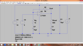
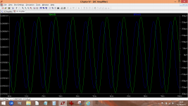
Example 1. A simple AC coupled single rail amp. The load is returned to the point marked ground. That point becomes an absolute reference. It is where all other values are measured from. To make this reflect real life there is a small (10ma) sine wave current taken from the supply. The supply has also series impedance such that this 10ma current will modulate the rail. Just as happens in a real design. The impedance might seem unrealistically high but consider an expiring 9 volt battery and its internal resistance. The amplifier is under a no signal condition with the input biased to the midpoint voltage (5 volts).

So that is the basic circuit. If we look at the output voltage and output current we can see they are miniscule. Theoretically it should be zero... are we seeing the supply rejection of the opamp come into play ?

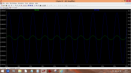
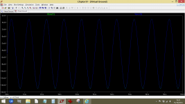
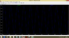
Now we change the amplifier such that the load is returned to the positive rail (which you imply above is at AC ground)

Again we look at the amplifier output. Look now at the scale and the amplitude of the signals. There is considerable rail disturbance flowing in the load. That is caused by the rails not being at the same AC impedance. It is a real world example of what happens.

A similar situation arises with a virtual ground configuration if the load or a feedback return is not referenced to the virtual ground point but rather to a rail instead. Having picked your point of reference that you are going to call "ground" or that you want signals referenced to then you have to stick to it.
Attachments
A similar situation arises with a virtual ground configuration if the load or a feedback return is not referenced to the virtual ground point but rather to a rail instead. Having picked your point of reference that you are going to call "ground" or that you want signals referenced to then you have to stick to it.
So back to my situation, what I would glean from your statement and post here is a confirmation of something I've observed. Even though I have developed a 1/2V-Gnd as a reference within my circuits, some have advised that I simply reference my external inputs or outputs to 0V, by letting my external signal ground reference be 0V, and simply use AC coupling. But I too have found that to result in more supply induced noise, particularly in a mixed signal situation where digital switching electronics exist on the same board. Despite all proper uses of ground planes and proper layout, sticking with the 1/2 V-Gnd both within the "box' and as an external signal reference has always resulted in audibly quieter circuits for me. And based on the capacitor between +V and 0V in your example, I'd coclude that even with my dubious inclusion of a capacitor from V-Gnd to 0V, exporting and importing V-Gnd consistently is still a the clear winner from a supply noise point of view.
So you can see why despite my new "add on" device running from the same supply, I really want to find a way to stick with the V-Gnd methodology that has worked so well in the past. Its just that this time, I have to "slightly" compromise the second "backup" V-Gnd by 50 ohms DC. It only remains to be seen whether some unknown "murphy-ism" rears its head in the AC realm. Hence, the capacitors between both my V-Gnds and 0 V, AND my constraint that the interconnecting cables be short. Those are just instinctive guesses at contributing to stability. Hopefully they are educated and good guesses which at the very least, don't hurt.
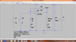
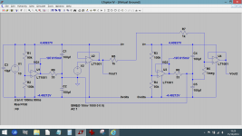
It all seems to work in simulation. Notice the deliberate imbalance of both virtual grounds. The output of the final stage still accurately reflects the input of the first. The current in the 33 ohm resistors are equal and opposite (-6ma and +6ma). There is no DC offset at either output. I deliberately added a -5mv offset to the input signal which is accurately passed through the system. I added a resistor to the first VG opamp because many opamps don't like to see capacitive loading directly on the pin although that really applies to small values. Anything large would kill any instability. Its there, it works.
If you use LTspice I can upload the file.
If you use LTspice I can upload the file.
Attachments
You should be able to get the differential down below 10mv (I would have thought so anyway). A big variable could be the opamps for the virtual ground. If these are bjt devices rather than FET they will have relatively large and slightly unpredictable input bias currents.
Oh by the way, these are TI parts, LME49721. They really are very good rail-rail (5V max) OP amps, and their offset V is only 0.3Mv. So I haven't really figured out why the difference between my V-Gnds was that much. But at elast i can say it likely is a true worst case.
It all seems to work in simulation. Notice the deliberate imbalance of both virtual grounds. The output of the final stage still accurately reflects the input of the first. The current in the 33 ohm resistors are equal and opposite (-6ma and +6ma). There is no DC offset at either output. I deliberately added a -5mv offset to the input signal which is accurately passed through the system. I added a resistor to the first VG opamp because many opamps don't like to see capacitive loading directly on the pin although that really applies to small values. Anything large would kill any instability. Its there, it works.
If you use LTspice I can upload the file.
Thanks. OK Mooly.. I think I'm confident enough to put this to rest now. Regarding LSpice, I do have the capability of generating the files from my DesignSpark PCB software, so maybe I'll try it with my own circuits (I need the experience doing so anyway). I guess for things like this, I probably wouldn't trust the simulation 100% anyway. But it doesn't hurt, and sometimes it does point out surprises.
...you're not explaining things well for someone without a grasp of the terminolgy. You need to be crystal clear and unambiguous.
This guy told me I couldn't possibly be right because he had 45 years experience.
You told me you couldn't just treat a rail as ground.
You mean like this?
An externally hosted image should be here but it was not working when we last tested it.
Now let me be crystal clear and unambiguous.
What you're conspiring at together is T1TS ON A BULL engineering. I tried to point you in the direction of doing something more elegant, but no, you pushed me to the point where I had to say it.
- Status
- This old topic is closed. If you want to reopen this topic, contact a moderator using the "Report Post" button.
- Home
- Design & Build
- Construction Tips
- Issue combining virtual Grounds