Shoog, what are the characteristics that make one particular pentode better than another for use in this circuit? Am I looking for maximum gm? How much current the pentode can sink into the load? A minimum amount of gain? A high value of ra? Maximum plate+screen grid dissipation?
I don't understand why 6J9P isn't a good choice here. It has high enough plate dissipation (3W) for it to work well with Ia = 9mA. It has higher gm than EL83. It has higher gain than EL83, but not by all that much (Aa-g2 is 24 for EL83, ~40 for 6J9P).
6AU6, by comparison, is designed to work with about Ia = 8mA, has gm = 5mA/V, max plate dissipation of 3.5W, Aa-g2 = 36. 6J9P looks like it's similar but with 3X the gm.
I can always remove the 9 pin sockets and put in 7 pin sockets. I have the type that fit. But again, if the 6AU6 work well enough, shouldn't 6J9P work even better?
I agree, it should do fine for your purposes.
My opinion on the best pentode would be does "the curves look linear" (EL83 looks excellent and that should be equally true at lower g2's), however its unpredictable what you will get if you don't give it the standing current it wants so maybe this is the wrong valve for this situation. Other than that if the standing current is at least twice the swing current you expect then just about any pentode will do service.
The final output impedance is also worth considering as it will dictate the feedback resistor you choose - but ultimately its absolute value is arbitary. I would tend to go for the lowest plate impedance pentode I could find to keep the feedback resistor as small as possible.
In all the implementations I have designed the plate load resistor and the feedback resistor are one in the same which tends to force the finals into a 100% feedback arrangment - giving no voltage gain but very low output impedance, surprisingly this makes the choice of pentode arbitary in terms of its plate impedance.
Shoog
Last edited:
This is looking promising...
How do I calculate the 'swing current'? (I'm not sure what that is, even.) Is it the current needed to drive the low impedance node at the final's input? If so, I see more math coming my way...
6J9P's ra is quoted at 100k. EL83 is much lower, I think 24k. Of course, EL83's ra will be higher at low current operation, so that might be evening the score between the two types.
That's how it is in Doug's E-Linear ST70. He puts a 30k feedback resistor from the output tube's screen grid+40% UL tap on the output transformer to the plate of the driver pentode. Does that change the amount of NFB around the output tube/final?
Sorry for the barrage of questions. I'm slowly beginning to see the light of understanding. I get all excited when that happens.
--
if the standing current is at least twice the swing current you expect then just about any pentode will do service.
How do I calculate the 'swing current'? (I'm not sure what that is, even.) Is it the current needed to drive the low impedance node at the final's input? If so, I see more math coming my way...
The final output impedance is also worth considering as it will dictate the feedback resistor you choose - but ultimately its absolute value is arbitary. I would tend to go for the lowest plate impedance pentode I could find to keep the feedback resistor as small as possible.
6J9P's ra is quoted at 100k. EL83 is much lower, I think 24k. Of course, EL83's ra will be higher at low current operation, so that might be evening the score between the two types.
In all the implementations I have designed the plate load resistor and the feedback resistor are one in the same which tends to force the finals into a 100% feedback arrangment - giving no voltage gain but very low output impedance, surprisingly this makes the choice of pentode arbitary in terms of its plate impedance.
That's how it is in Doug's E-Linear ST70. He puts a 30k feedback resistor from the output tube's screen grid+40% UL tap on the output transformer to the plate of the driver pentode. Does that change the amount of NFB around the output tube/final?
Sorry for the barrage of questions. I'm slowly beginning to see the light of understanding. I get all excited when that happens.
--
By swing current I mean the current difference between the Peak to Peak of the signal coming off the plate.
Shoog
In this case the feedback ratio is mostly defined by the 40% tapping with the driver impedance having a lesser impact.That's how it is in Doug's E-Linear ST70. He puts a 30k feedback resistor from the output tube's screen grid+40% UL tap on the output transformer to the plate of the driver pentode. Does that change the amount of NFB around the output tube/final?
Shoog
By swing current I mean the current difference between the Peak to Peak of the signal coming off the plate.
I'm sorry, I don't understand.
Is that the pk-pk signal output from driver pentode's plate?
To determine signal current, don't I need to use the load impedance? If the pk-pk signal voltage is 70V (35V peak signal at the 6L6 grid), what load exactly is that working into? If it's the ra || RL || Rg that's also at work in the feedback equation, then the current would be...
70V / 15k = 0.004667
Double that would be 9.3mA.
That means the 9mA from the 6J9P is just barely adequate. If that's right, then I see what you mean.
--
You've got it there.
2x is just my rule of thumb.
The results of your simulations should give you a better idea of what is going on. Its very interesting to see the wave form's for both current and voltage at the plate of the driver. Its not what you would normally expect.
Shoog
2x is just my rule of thumb.
The results of your simulations should give you a better idea of what is going on. Its very interesting to see the wave form's for both current and voltage at the plate of the driver. Its not what you would normally expect.
Shoog
Last edited:
You've got it there.
The results of your simulations should give you a better idea of what is going on. Its very interesting to see the wave form's for both current and voltage at the plate of the driver. Its not what you would normally expect.
Thanks for your help with this. It's interesting stuff, and you've been very generous. Much appreciated.
I'm just about to go home and will be able to run all this in LTspice. I'll post pics of the waveforms, just for yucks. Should be interesting...
--
This evening, I've put in some time modeling E-Linear 6L6 amps instead of continuing to wire my other amp. It's been interesting.
Both models I ran use a Dyna A470 OPT model with two 6L6GC in UL config with B+ of 450V. The output stage has a 650 ohm cathode resistor for each 6L6, bypassed with 330uF. I haven't tried it with a shared cathode resistor yet.
Candidate Number One has an LTP made of two 6J9P pentodes.
Candidate Number Two has an LTP made of two 6P15P (or EL84) pentodes.
Interesting thing #1 is that if I give the screens a separate 150V supply without a resistive load in series, distortion goes way up. It seems the screens like a large value resistor there (different for each tube, but all are >50k). Even a 150V supply with a 2.2k load resistor before the screens doesn't work well. Why is that? And how would I implement a regulated screen supply? Regulated voltage straight to the two 1k screen stoppers and then to the screens (bypassed to cathode with 3uF or so)? Or does there need to be a large load resistor going to the screens?
Because of that weird finding with the 150V supply, all sims were done with a large value Rsg -- 50k for the 6J9P, 75k for the 6P15P. With those in place, simulated THD at 1W out is 0.02% or less (which is damn good!).
The 6P15P doesn't do very well with only 10mA plate current, so I raised it to 13mA, with about 2mA drawn by the screen grid. That helped quite a bit. Unfortunately, it means the total draw for two channels will be 290mA.
Interesting thing #2 is that the high power output waveform looks better with the 6P15P as the driver. The simulated maximum output power is 40W RMS at <= 0.5% THD(!!). The max power out is the same with the 6J9P as the driver, but the output waveform looks more jagged.
I wish it was possible to include four 6P15P or EL84 as the driver pairs, but I think the power transformer just won't support it. It's looking like it will have to be 6J9P for the LTP.
Does anyone know of a good 6J11P spice model? I don't know of one, and googling didn't find one.
--
Addendum:
- If C2 and C3 are 1uF or less, there's a peak in the bass response right about 10Hz. Increasing those to 2.2uF flattens out the peak and the circuit is -1dB at 4.5Hz. I think I'd put an input blocking cap to make the response -1dB at 20Hz. It's a tube amp, it can't make really low bass, so why stress the OPTs and cause extra IM distortion?
--
Attachments
Last edited:
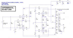
Pentode question -- What values are acceptable for the 6J9P screen stopper resistor? In the schematic from the previous post, those are R9 and R12. Is 10k way too large a value?
I'm finding that there's a lot of variance between these pentode models. So far I have two 6J9P models, an E180F model (Ayumi N.) and a 6688 (also Ayumi N.). The E180F and 6688 models aren't too far off from each other, but the two 6J9P models are a bit off the charts. In the same circuit, if I use 60k for R13 (Rsg in Doug's schematic), the 6688 and E180F models get me 135V to 145V on the screen. But the 6J9P models are way off. The 6J9P4 model (in the schematic from my last post) gives me 100V at the screen, the 6J9P5 model gives me 200V.
However, if I put in 10k screen stoppers (R9, R12), the 6J9P5 model gives me 165V there. That's still too high, but at least it's in the ballpark.
What will putting in 10k grid stoppers do, besides reducing gain?
--
Have you considered sacrificing a tiny bit of output power in order to use the EL83 as drivers ?
Gary Pimm explained to me once that g2 acts as a feedback element so adding a series resistor should reduce distortion at the price of a little gain. Also the 50K resistor is shared between the LTP which means that as pentode goes up in screen current the other goes down. This means that the current through the resistor should be virtually constant. I have applied similar values in some of my designs.
Shoog
Have you considered sacrificing a tiny bit of output power in order to use EL83?
Actually, output power is slightly increased if i use EL83, I assume due to better drive at high levels than is possible from 6J9P. I'll need to decrease idle current through the 6L6's to make room for EL83's. That will increase distortion in the output stage, but that is where the feedback is, so maybe that will be OK. I'll have to run that through spice...
...
Yes, I have noticed that too, screen resistors introduce negative feedback. The problem with that in this design is that we do not want this effect, we need to have the high output impedance of a pentode.
In the LTspice sim, feeding 150V straight to the screens increases distortion by 10x as compared to a 430V supply with series resistor. Gain wasn't reduced by very much. I don't know why.
I run 6P15P in drivers with 4 mA current (triode mode). The best ever linear swing. SPICE models differ from the life.
Thanks for that insight. 4mA plate+screen current in triode mode? That's amazing that it works at all. I guess that's a hefty recommendation to go ahead and use the 6P15P with something like 9 or 10mA plate current. It looks like the votes are in and that's what I should try.
Next steps will be to finish up my ill-advised cathodyne-driven PP 6L6-triode amp. It's almost done. After that, strip out the remnants of the last circuit that was in this Stereo 70...
--
- Status
- This old topic is closed. If you want to reopen this topic, contact a moderator using the "Report Post" button.
- Home
- Amplifiers
- Tubes / Valves
- Is there a 9-pin mini equivalent of 6AU6?