Hi tinkerbell,
My previous post outlines what I have done of my amps, so I can say it works. You proposal is a little different but looks OK. I haven't tried it so can't say for sure it will work. People often build monoblocs that have both channels completely separate.
What I suggest is you make you earth scheme flexible enough to make it easy to change. I often use spades and connectors so I can try different arrangements.
BTW: The BrianGT Gainclone has separate earths on the PSU pcb and a star earth on the amp PCB, similar to your proposal.
Hi,
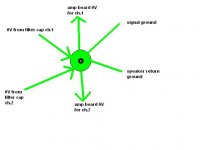
The speakers returns should connect direct to the star earth .
Check out the signal ground from the input terminals, they should go to the signal ground on the amp PCB or an appropriate clean ground.
You should have two ground returns to the star earth from each amp PCB, a signal ground and a power ground. All dirty returns (decoupling and zobel) should be connected to the power ground and not the signal ground. Alternatively the zobel can be mounted off board on the speaker output terminals.
Next the safety earth on the mains input needs a resistive connection (and/or //capacitor) to ground. BUT which ground???
keep it inside the PSU casing and connect to ONE power ground, or take a separate wire all the way to the star ground, or to the PCB clean grounds? Which one? or all of them (just kidding).
Andrew T - please forgive my newbieness, and this relates to your first post in this thread - what is a "dirty ground"? and what is a "clean ground"?
also - what is the purpose of the resistor between the PE and power ground? Rod Elliot talks of a capacitor, but does not mention a resistor...
is it a safety thing (probably) or a filtering thing (possibly)?
also - you seem to indicate that the signal ground should be kept away from the "dirty grounds"
how is this done with a single "star" ground point?
is the signal ground preferrably connected directly to the amp. board?
with the speaker returns connected to the power ground (star point?)
but these will all be connected anyways due to the star earth pattern on the PCB board???
BTW - is this simplified attached picture of how the grounds connect in a star correct???
Attachments
Hi, ")
Basically, yes, it's what I meant.
Well, you *could* connect both PSU lines together, but you shouldn't do it. The reason why even separate supllies would 'cross-talk' is that they would share a common current path, i.e. a piece of wire (with internal resistance) that would 'modulate' the ground potential, thus making it 'dirty'. I'll get back to this in a minute...
Nope, sorry. You could give this a try (as it is easy) but it could sacrifice distortion performance of your amplifiers significantly (and you probably only recognise it at loud listening levels, i.e. never in case you don't compare).
It's not too high, I was just asking what you intended with the resistors...
Basically, 'bleeding' is another safety feature. The capacitors are happy with storing charges, and their internal resistance would dissipate the stored energy over time, anyway.
But it helps to have the supply discharged in a 'defined' amount of time. First, it helps to prevent arcing when handling with the cabling during testing or setup, and second it helps to prevent arcing even days later, when you've already forgotten when it was turned on the last time...
I've seen an ugly picture of a guy's hand on the net. He had an accident during repair of a low voltage power supply that was not yet 'bleeded'. His wedding ring shorted the capacitor terminals and melted. I'd say he lost the finger, at least partially...
Just like the others, I would recommend properly calculated 'snubbering' at the amplifiers.
The connections between the respective capacitors are just right. Now let me explain why, because it has something to do with...
Wire has resistance, and Ohm's law dictates that a resistance, conducting current, drops voltage. This voltage is an AC waveform depending on current draw and wire resistance.
A 'clean' ground (that is not influenced by such introduced AC modulation) gets dirty just by connecting it to the (ground) return path of a part in the amp which draws higher currents. If, say, your signal input shares a piece of ground wire with your power ground on the amps (for local bypass capacitors and snubbers), then the signal ground will get modulated with the AC voltage that the piece of wire drops (due to 'shared' currents from the amp board).
It's as basic as Ohm's law R=U/I. The voltage in a piece of ground wire can thus be calculated as U=R*I, with R from a table (depending on your wire material, width/cross-section and length) and the (maximum) current that flows through that resistance.
Say, your shared ground has 10mOhm of internal resistance and it conducts 1A. This translates to U = 10mOhm*1A = 10mV of modulation amplitude on your signal ground. As the amplifier actually amplifies the difference between it's input wire and it's respective ground, a 10mV 'hum' between those two lines will be 'seen' by the amp.
If you amp has a gain of (say) 20, this hum gets amplifed to 10mV*20 = 200mV at the speaker output. Clearly audible, as it will produce P = U*U/R = 200mV*200mV/4Ohms = 10mW into a speaker.
It's a filtering thing. It's not absolutely neccessary and could be a piece of wire in case of a 'perfectly' working grounding scheme. But a resistance between circuit (power) ground and PE damps ground loop currents a little, without ruining safety too much.
Yep, except that the speaker returns could also connect separately.
Cheers,
Sebastian.
tinkerbell said:you are absolutly right - i had been viewing my PSU + amp boards in total isolation - completely forgeting where my signal comes from - another components ground!
this makes me think the amplifier section (made up of two seperate amp boards) needs to have a common ground to reduce any loop hum as the signal ground will be shared.
is this right (ie what you have been trying to say)?
Basically, yes, it's what I meant.
ok then - for some reason i thought that two seperate transformers and their respective rectifier/filter cap. circuts should NOT connect their 0V lines together as there would be some sort of 'cross-talk' of 'dirtyness'
if i *could* connect both seperate PSU 0V lines together att the PSU section, with one 0V cable running from the 6 way terminal, leading to one common point in the amp section, then 'starring' to the 0V in for each amp board - would this work?
Well, you *could* connect both PSU lines together, but you shouldn't do it. The reason why even separate supllies would 'cross-talk' is that they would share a common current path, i.e. a piece of wire (with internal resistance) that would 'modulate' the ground potential, thus making it 'dirty'. I'll get back to this in a minute...
to surmise - will it be OK to connect both my 0V lines at the output of the PSU enclosure and send a single line to the amp enclosure then split wires off to each amp board 0V point?
Nope, sorry. You could give this a try (as it is easy) but it could sacrifice distortion performance of your amplifiers significantly (and you probably only recognise it at loud listening levels, i.e. never in case you don't compare).
re: bleeder resistor - yes - it was late when i drew that picture (lol!)
so are you saying 6800ohm is too high? maybe 4700ohm or less?
It's not too high, I was just asking what you intended with the resistors...
Basically, 'bleeding' is another safety feature. The capacitors are happy with storing charges, and their internal resistance would dissipate the stored energy over time, anyway.
But it helps to have the supply discharged in a 'defined' amount of time. First, it helps to prevent arcing when handling with the cabling during testing or setup, and second it helps to prevent arcing even days later, when you've already forgotten when it was turned on the last time...
I've seen an ugly picture of a guy's hand on the net. He had an accident during repair of a low voltage power supply that was not yet 'bleeded'. His wedding ring shorted the capacitor terminals and melted. I'd say he lost the finger, at least partially...
also - do you think the rectifiers need bypass capacitors too - like 100nF?
Just like the others, I would recommend properly calculated 'snubbering' at the amplifiers.
does that diagram have three 'earth' points or just one?
it looks like three to me - two in the PSU enclosure and one in the amplifier enclosure...
if it is just one, then i will be VERY happy,
if it is three - how can i resolve this when using two seperate enclosures?
The connections between the respective capacitors are just right. Now let me explain why, because it has something to do with..."dirty ground"? and what is a "clean ground"?
Wire has resistance, and Ohm's law dictates that a resistance, conducting current, drops voltage. This voltage is an AC waveform depending on current draw and wire resistance.
A 'clean' ground (that is not influenced by such introduced AC modulation) gets dirty just by connecting it to the (ground) return path of a part in the amp which draws higher currents. If, say, your signal input shares a piece of ground wire with your power ground on the amps (for local bypass capacitors and snubbers), then the signal ground will get modulated with the AC voltage that the piece of wire drops (due to 'shared' currents from the amp board).
It's as basic as Ohm's law R=U/I. The voltage in a piece of ground wire can thus be calculated as U=R*I, with R from a table (depending on your wire material, width/cross-section and length) and the (maximum) current that flows through that resistance.
Say, your shared ground has 10mOhm of internal resistance and it conducts 1A. This translates to U = 10mOhm*1A = 10mV of modulation amplitude on your signal ground. As the amplifier actually amplifies the difference between it's input wire and it's respective ground, a 10mV 'hum' between those two lines will be 'seen' by the amp.
If you amp has a gain of (say) 20, this hum gets amplifed to 10mV*20 = 200mV at the speaker output. Clearly audible, as it will produce P = U*U/R = 200mV*200mV/4Ohms = 10mW into a speaker.
also - what is the purpose of the resistor between the PE and power ground? Rod Elliot talks of a capacitor, but does not mention a resistor...
is it a safety thing (probably) or a filtering thing (possibly)?
It's a filtering thing. It's not absolutely neccessary and could be a piece of wire in case of a 'perfectly' working grounding scheme. But a resistance between circuit (power) ground and PE damps ground loop currents a little, without ruining safety too much.
BTW - is this simplified attached picture of how the grounds connect in a star correct??? [/B]
Yep, except that the speaker returns could also connect separately.
Cheers,
Sebastian.
OK, thanks again Sebastian and Andrew!
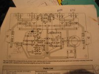
so if this is a attached picture of the amp circut, is it *correct* to have my 0V line connect to the GND point and my signal ground connect at INPUT point and my speaker ground connect at the SPEAKER point - being all connected to a "dirty" gound point?
or do they become dirty when you are running a length of wire to them?
will the resistance of the PCB tracks make the signal ground "dirty"?
or is this a well designed PCB?
you mention snubbing at the amplifier - can you identify if this amplifier board has this - is it the 100uF electro and the 0.1uF mylar between the the +/-57V rails and the 0V ground?
and if you say my twin enclosure diagram has the 0V lines connected "just right" - are you saying that the layout for my connections as best as we can get with a twin enclosure setup?
regards,
david..
Attachments
Hi David,
the star ground in post 23 needs another signal ground (these are your ch1 & ch2 clean grounds). The 0V grounds are your dirty grounds (power grnd).
The pcb layout in post 25 mixes clean and dirty together. Some applications (& designers) prefer this solution.
I suggest you alter it to separate the 8 decoupling capacitors.
If it is already prepared you can run insulated wire to the large speaker land and cut the 3 dirty connections before the (now) clean ground. The 2 wire links just run to new drilled holes in the speaker land.
The zener could do with a cap in // to reduce noise and stiffen the output voltage especially at high freq.
I think Sebastian has answered the query about ground located in amp box or in the PSU;- run both a clean and a dirty return back to the PSU and locate your star ground in the PSU box. Correct me if I'm wrong. or any other suggestions for the master ground???
Finally the safety gound thing is filtering;- some deigners use a switched set of resistor//cap//diodes//dead short connecting safety to star. If you omit the resistor and use the dead short the amp has 2 connections to chassis and a potential hum then exists. A bit complex but your separate PSU may deserve this, try different connections until a quiet solution emerges.
cool, thanks Andrew - maybe that is why i was so confused about grounding - the PCB had all the grounds to the same point and i assumed that this was "optimal"
ALSO - i powered up the power supply and amp board yesterday.
set the VR and let it settle for a while, then fused it up and attached a speaker to it, and it was silent, just a tiny hiss with my ear right next to the tweeter (almost touching).
then i attached the signal (from PC soundcard) and i think i could hear my PC fan noise through the speaker, but very quiet. the amp plays music VERY cleanly too.
i could hear no hum at all, despite my simplistic hookups...
maybe i am worried about something that wont be an issue, or will it *become* an issue when i use 5x as much in lengths of wire to hook it all up?
i guess as you say - i will have to wait untill the modules are enclosed and operating to determine the level of hum that *may* be present, then address it through trial and error changes
i will also look at seperating the dirty from clean grounds on the PCB...
regards,
david..
- Status
- This old topic is closed. If you want to reopen this topic, contact a moderator using the "Report Post" button.
- Home
- Amplifiers
- Solid State
- is my PSU layout OK?