Here's one that is baffling me.
The original problem was that when I tried to build a multiplexed LED display the LEDs were too dim to be visible under normal lighting.
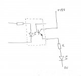
Here is a little test circuit that I'm playing with around an IL-1 opto-isolator.
The circuit is fed with a 5V 333Hz square wave 1mS (ON) 2mS (OFF).
Now Ic(max) of the IL-1 is 50mA (cont) and 400mA (t(on) < 1mS).
So ignoring Vce of the IL-1 I tried R = 220R and measured the voltage across R with a 'scope. V=1.5V so I=7mA.
A lot lower than I expected.
OK I thought lets try R = 100R. V=0.7V so I=7mA.
Weird.
OK I thought lets try R = 47R. V=0.34V so I=7mA.
Weird.
I'm missing a trick here somewhere but I can't figure out where.....
The original problem was that when I tried to build a multiplexed LED display the LEDs were too dim to be visible under normal lighting.
Here is a little test circuit that I'm playing with around an IL-1 opto-isolator.
The circuit is fed with a 5V 333Hz square wave 1mS (ON) 2mS (OFF).
Now Ic(max) of the IL-1 is 50mA (cont) and 400mA (t(on) < 1mS).
So ignoring Vce of the IL-1 I tried R = 220R and measured the voltage across R with a 'scope. V=1.5V so I=7mA.
A lot lower than I expected.
OK I thought lets try R = 100R. V=0.7V so I=7mA.
Weird.
OK I thought lets try R = 47R. V=0.34V so I=7mA.
Weird.
I'm missing a trick here somewhere but I can't figure out where.....
Attachments
Not an unexpected result I think. Try an opto with a higher "current transfer ratio".
Current Transfer Ratio (CTR) and Response Time of Photocouplers / Optocouplers | Renesas Electronics Europe
Are you driving the opto hard enough ?
Current Transfer Ratio (CTR) and Response Time of Photocouplers / Optocouplers | Renesas Electronics Europe
Are you driving the opto hard enough ?
I think tbh you really need a high transfer ratio device. They are really darlingtons internally and ratios up to 15000% (maybe more nowadays) are available.
Buy Optocouplers Optocoupler Transistor O/P, 300V, SMD4 Lite-On LTV-852S-TA1 online from RS for next day delivery.
Buy Optocouplers Optocoupler Transistor O/P, 300V, SMD4 Lite-On LTV-852S-TA1 online from RS for next day delivery.
The problem is I'm playing with PICs. The maximum output current of the PIC that I'm using is only 25mA per pin. The LED displays need about 160mA with the low duty cycle to achieve full brilliance.
I've now increased the opto LED drive to the maximum of the PIC (ie 25mA) and with R = 100R I'm now seeing ~ 13mA through R.
I'm guessing that the IL-1 I'm playing with is a bit outdated.
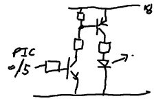
The LEDs are Common Cathode so I've had to add an amplifying element between Vcc and the Anodes to increase the available current. Using PNP transistors isn't viable because of the 5V logic level of the PIC. My solution was to try opto-isolators. I'm only playing at the moment and thinking with my fingers and bits box.
I've now increased the opto LED drive to the maximum of the PIC (ie 25mA) and with R = 100R I'm now seeing ~ 13mA through R.
I'm guessing that the IL-1 I'm playing with is a bit outdated.
The LEDs are Common Cathode so I've had to add an amplifying element between Vcc and the Anodes to increase the available current. Using PNP transistors isn't viable because of the 5V logic level of the PIC. My solution was to try opto-isolators. I'm only playing at the moment and thinking with my fingers and bits box.
Last edited:
My mistake was that I opted to drive the displays with an 18V battery..
I've got to maintain 0V integrity because of other logic elements in the circuit.
I suppose I could drop Vcc (LED) down to 5V.
Originally I used 2N3906 (PNP) transistors to supply the additional current but then I lost 0V integrity because +18V(LED) had to be tied to +5V(PIC) so that the transistors would operate. That it what took me down the opto route.
A picture paints a thousand words.
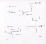
The PIC and the CD4514 both share the same power supply so 0V integrity must be maintained.
The PIC outputs +5V (Logic 1) and 0V (Logic 0) - nothing unusual there.
I'm not familiar with "level shifters", how could they be used in this situation.
The 16 x diodes are the LEDs. The PIC 25mA supplies are from two ports supplying 16 x LED segment drive. The CD4514 is the multiplex decoder with a BD681 for each display.
Why 18V, I just happen to have an 18V battery doing nothing. I'd need another supply anyway as the PIC board can only supply 500mA or so.
Attachments
Last edited:
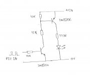
You probably could do it with a transistor/s and level shifting resistors. A PNP would give the wrong result though compared with the opto arrangement, the PIC output going high would be turning off the transistor. Two transistors, an NPN and PNP per LED should work with level shifting (two resistors) to the first transistor.
The top resistor is just to keep the PNP base from "floating" so can be high, say 100K. The other resistor determines base current so use say 10K. The resistor to the base of the first transistor should be say 10K. If the PIC output actively pulls the port to 0 volts no other resistors needed. If the PIC outout "floats" (I'm sure it won't) when off then a base to emitter turn off resistor is needed, say 100K
")
You may wish to add a resistor from the base to ground on that first transistor to shift the threshold closer to mid supply. With a PIC being able to get within millivolts of ground, it isn't a big issue though.Like this.
OK. I've built the "level changer" and I've got the LED flashing at 333Hz.
Even with the LED current set to 75mA the LED is quite dim with a 1:3 duty cycle.
Bearing in mind that the finished project will have 16 displays so the duty cycle will be 1:16, how do the manufacturers get the LEDs to light at full brilliance ?
I'm using an ON time of 1mS at the moment due to 16 x 1mS being close to the point where the human eye will detect flashing LEDs.
Attachments
- Status
- This old topic is closed. If you want to reopen this topic, contact a moderator using the "Report Post" button.
- Home
- General Interest
- Everything Else
- Is my Home Ohm free ??