jh6you said:Enjoy your laziness! One of my daily work is about the stiffness of structural members.
Yeah? I know a hooker who's in the same line of work. Small world, eh?
")
se
Steve Eddy said:
Small world, eh?
se
Must... resist... commenting... hold... me... back...
Or in another way, radiating the vibration energy away....Steve Eddy said:
Damping is loss. The converting of mechanical energy into thermal energy.

WOODY WOODPECKER....
Hi,
ROTFLMAO.
No wonder you prefer wood as a damping material...
Cheers,
Hi,
Yeah? I know a hooker who's in the same line of work. Small world, eh?
ROTFLMAO.
No wonder you prefer wood as a damping material...
Cheers,
jh6you said:Or in another way, radiating the vibration energy away....
Yup. Never to return.
se
Re: WOODY WOODPECKER....
Yup. Good wood can make a babe quite damp.
se
fdegrove said:No wonder you prefer wood as a damping material...
Yup. Good wood can make a babe quite damp.
se
Nobody took seriously the idea I brought about the water vibrations barrier. It's a pitty because I think it can give nice answers. Maybe you thought it was a joke?
I last had a waterbed around 10 years ago. Pity, would have tested your idea with pleasure.
peter
JOE DIRT® said:a sarcastic thread ....shame on you all
Whoever thought that this thread originated a joke, was mistaken. I started with an idea of using sort of isolation for the chip with water, which led me to use of copper tubing. Well, I didn't use any fluids, but copper tubing stayed in my new project.
The pic represents the initial concept of a monoblock amp with integrated PS. The amp module is built around 1.25" copper tubing, mounted in sort of aluminum frame, which eventually will be one piece (2 x 3" square tubing) with cut out for ceramic heat vent (bought conveniently at HD
). The copper heatsinks will be isolated from aluminum with either wood, polycarbonate or neoprene. The transformer housing will be attached from the bottom.Attachments
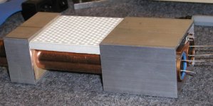
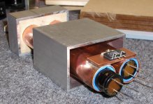
The chip is mounted on the tubes, by using a copper plate, which is soldered. Initially I was considering to place filter caps outside the tubing, but somehow they didn't fit anywhere, so I decided to place them inside ea. tube. I will take off their plastic jackets and use neoprene padding to both damp and position them.
I am still not sure if it's a good idea to use the whole copper assembly as a negative rail. In this way, I wouldn't have to use any insulating pads under the chip and the connections would be simplified, but I don't know if this will affect other things (like for instance the capacitor inside the tubing).
Anyway it seems like a good start, makes for very compact layout and I am able to use copper heatsinks instead of aluminum (which come actually very cheap). With this layout, it would be also very easy to use PCB, but I didn't decide on this yet.
I also think it's as original as it can be, and quite refreshing idea too. The "sound" of the copper tubes can be tuned with filling the cavity with sand.
I am still not sure if it's a good idea to use the whole copper assembly as a negative rail. In this way, I wouldn't have to use any insulating pads under the chip and the connections would be simplified, but I don't know if this will affect other things (like for instance the capacitor inside the tubing
).Anyway it seems like a good start, makes for very compact layout and I am able to use copper heatsinks instead of aluminum (which come actually very cheap
). With this layout, it would be also very easy to use PCB, but I didn't decide on this yet.I also think it's as original as it can be, and quite refreshing idea too.
The "sound" of the copper tubes can be tuned with filling the cavity with sand.Attachments
Actually I have no experience in that area at all. The copper would be carrying negative rail potential, the chassis would be grounded (aluminum). I know that Cello amps had heatsinks connected in this way too and output devices were powered directly from the heatsinks (no insulators).

LM3875TF
Hey Peter,
I don't undertand your concern about isolation.
Why don't you simply use the isolated version of the chip?
Looking at your project, oh yes, it looks very nice, as usual.
But I think that the copper heatsink is small an the tubes will get hot.
And the caps won't last long if they're always hot.
Oh, and those BGs are expensive.
The advantage of using not isolated version is better heat transfer and if used without pad it can be directly connected to negative rail, formed by a copper heatsink. This could yield possible advantages. In this way a smaller heatsink is also acceptable.
I don't know about you, but my GCs very rarely get hot, usually they only warm, so I'm not afraid about those BG caps. It's not like Alephs, where temp. is always 50 deg C or more.
Now, I could go the easy way and use aluminum square tubing as heatsink surface, but this project is more advanced and special resosnance control approaches are being incorporated
Peter Daniel said:
I don't know about you, but my GCs very rarely get hot, usually they only warm, so I'm not afraid about those BG caps. It's not like Alephs, where temp. is always 50 deg C or more.
Ah...
Yes, mine doesn't get too hot, as yours.
But my speakers are more difficult to drive than yours, and as everything sounds good to me now, lately I push it hard a little, because it feels good.
Yesterday it was Ben Harper at half volume.
It gets a little hot after a while.
My half volume may be a little more than 1/4 volume for you, as your speakers are much more sensitive than mine.
But I love my speakers more than you!

Just joking, Peter...
Anyway, I don't know what you intend to do with this amp.
If you sell it, you'll have to expect everything.
Peter Daniel said:You have a point too, but my thinking is as follows: even if the amp is pushed and gets hot, it shouldn't be more than lat's say 3 hours a day (on average) and the caps are rated 85 deg, so it still should be fine
Aha, I've got you!
I'll remind you that when the things are really playing well I can't stop listening.
And, as you, I could listen for 8 hours.
Now, seriously, in a test I did with some Allison 4 ohm speakes, at very loud volumes I could at a point hear the thermal protection in action.
It reduces the volume.
And let me remind you that the protection kicks in at 150ºC!
Can you guarantee that anybody will use your amp for a party with 4 ohm speakers?
Peter;
I agree that the copper tubes should be exposed. They are perfect "form follows function" elements. Also they are shielded if they are grounded instead of being a live connection. Of course if they were hollow, with the components in a box outside the base, they would be very efficient heatsinks if you let air rise throught them like a chimney. Or use 2 tubes next to each other- one for the components or wait!! a "T" connector with the components in a side tube perpindicular to the cooling tube. Hmmm that might not look as elegant.
Just stand the project in the photo on end like 2 columns. The larger rectangular box is like a base plinth the smaller like a capital. (can you tell I'm an architect )Lose the heat vent.
OBOY !! : have the "live" component tube as you showed, but put it inside a grounded biggertube with 1/4" min. clearance between the 2 which would work as a stack, RFI shielding, vibration shielding. OK to sum up I really like the big copper tube idea (wayy better than the water).... actually you could fill the space between the 2 with water..... stop me someone!
Just some ideas to work with
I agree that the copper tubes should be exposed. They are perfect "form follows function" elements. Also they are shielded if they are grounded instead of being a live connection. Of course if they were hollow, with the components in a box outside the base, they would be very efficient heatsinks if you let air rise throught them like a chimney. Or use 2 tubes next to each other- one for the components or wait!! a "T" connector with the components in a side tube perpindicular to the cooling tube. Hmmm that might not look as elegant.
Just stand the project in the photo on end like 2 columns. The larger rectangular box is like a base plinth the smaller like a capital. (can you tell I'm an architect
)Lose the heat vent.OBOY !! : have the "live" component tube as you showed, but put it inside a grounded biggertube with 1/4" min. clearance between the 2 which would work as a stack, RFI shielding, vibration shielding. OK to sum up I really like the big copper tube idea (wayy better than the water).... actually you could fill the space between the 2 with water..... stop me someone!
Just some ideas to work with
- Status
- This old topic is closed. If you want to reopen this topic, contact a moderator using the "Report Post" button.
- Home
- Amplifiers
- Chip Amps
- Is LM3875 chip waterproof?