I build every amp input like that. For me it is standard.
I failed to mention that that input is the start of a star of stars. No loops.
The Signal Ground star can be physically located in a number of positions and the schematic is still identical.
Slide the SG star over to touch j1-1 and you have Leach's/ Self's option.
Slide the star over to the right to keep everything very close and compact next to the -IN pin and it works great for opamps.
Slide the star down and set R3 to 0r0 and you have a monoblock amplifier where Power and Signal are starred on the PCB.
What is sad is that National do not show this as typical and instead show a stripped down version that can suffer instability as the preferred implementation.This is the way to connect every AC coupled amplifier.
I failed to mention that that input is the start of a star of stars. No loops.
The Signal Ground star can be physically located in a number of positions and the schematic is still identical.
Slide the SG star over to touch j1-1 and you have Leach's/ Self's option.
Slide the star over to the right to keep everything very close and compact next to the -IN pin and it works great for opamps.
Slide the star down and set R3 to 0r0 and you have a monoblock amplifier where Power and Signal are starred on the PCB.
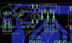
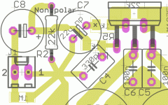
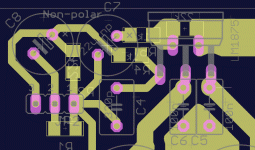
In my design I moved my star, so that everything has the shortest possible traces, but also similar length, except the trace with the 10R to ground is quite long but very thick... I suppose a picture is worth a 1000. I see the first resistor's first function as being a cable termination, thats why I place it at the last point any wire connects to, rather than say at the input socket, and then have a long piece of wire to the input cap, which combines as a secondary function of high-passing the signal.
Attachments
Last edited:
Yes its a bit of a hybrid a sort of compromise if you will between available parts, knowledge of best practice, etc...
I'm trying to understand the R2 R3 thing, are you saying it would be more correct to return R2 with the trace from R1 to ground, or that each should have its own return like in the schematic?
I'm trying to understand the R2 R3 thing, are you saying it would be more correct to return R2 with the trace from R1 to ground, or that each should have its own return like in the schematic?
Last edited:
It might help understanding the input schematic if you temporarily remove R3.
You are left with J1-1 & 1-2 where Signal Hot and Signal Return come in and the two input filters.
The amplifier with it's NFB loop measures the voltage across R2. That signal is magnified and sent to the output.
The signal across R2 must not be contaminated by any non audio signal nor interference.
This is why the Signal Ground must not be directly connected to the Power Ground nor to the PSU Zero Volts point.
Now take that same input circuit and imagine where the current flows from the source, around the input circuit, out through Signal Return back to the source. That LOOP must be signal only. No other signal can be allowed to share any part of that loop sending a non signal current through even a small portion of that LOOP.
Now put back R3. It provides the voltage reference to allow the output to match/follow the input.
Inserting R3 and connecting it to the PSU Zero Volts or to the Power Ground does not allow those other (non signal) currents to enter that LOOP and SHARE a length of that signal loop. The PSU or Power Ground interference arrives at the top of R3 but cannot go anywhere.The contaminating current would need it's own entry and return points in the signal loop. There is a potential "entry" point but there is no exit/return. No contaminating current can flow from Power Ground into the Signal LOOP.
Last edited:
I prefer the previous input layout. I liked the compact +IN, -IN, R2, R4.
Consider the possibility that C7 may need to be physically bigger. 150uF to 220uF electrolytic with a diode to prevent reverse charge >0.7Vdc.
Also consider adding inverse parallel diodes across the 10r to the main audio ground. And maybe a tiny ceramic cap as well.
A slight improvement in operational flexibility can be obtained by adding a signal trace to the previous layout.
Instead of a 0.2" pin pitch screw down terminal block, insert a 3pin single in line 0.1" pin pitch in the same location. Pin 1 remains as you have shown. Pin 2 moves to the cross in between your two existing pins. Pin 3 goes where you currently have Pin 2.
Pin 1 is Signal Return.
Pin 2 is Signal Hot AC coupled.
Pin 3 is alternative Signal Hot DC coupled. This pin is connected to the far side of C8 to bypass the cap and connect direct to R2 & R4.
Jens showed this gem in his Leach clone.
I attached the Signal Hot and Signal Return to the bottom of the PCB where the pins are soldered in.
On the top side I use a 0.1" computer shorting socket.
Park it on Pin 1 and your amp is AC coupled.
Short across PIN 1 to Pin 2 and you have the "test amplifier set up" with shorted input.
Short across Pin 2 to Pin 3 and your amp is DC coupled at the input only. This allows a source item that already has a DC blocking cap that cannot be easily bypassed to become the only input DC block. You don't need two series connected DC blocking caps.
Jens was brilliant providing us with this extra third pin. Worth copying on every amplifier you make.
Two final points.
Orient all your electrolytics in the same direction. Makes installation and checking later much easier.
Provide optional pin pitch pads for as many capacitors as you have space for, without altering your layout.
Last edited:
Wow, thats alot of data... I hope I got it right, appart from the size of the NP caps which will be scaled to real world parts I will use in the end... saw some pretty film caps in one of the threads this afternoon which I can still fit on my board. But I want to ge this grounding and coupling thing perfected.
Attachments
Sure, why not, I think with Andrew's help we might even perfect the deadbug layout; the chipamp everyone should start with.
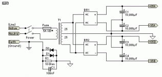
Hi Andrew, regarding the diodes and cap to ground, I know Rod Elliot uses a similar config, BUT, he seems to use it to bridge Between case ground terminal and power ground star. (image attached)
So my question is, do you think the disconnect network should be where you suggested, or as Rod suggested. I know you are very good at this, but maybe it was late and seeing only a piece of the layout you got confused... just want to doublecheck.
Your way would give protection to the SG but leave the PG with an uninterupted ground path, but as it is not the route to PG, would one still need to use such big components, i.e. 5A diodes, and high power resistor?
Its a might fine subcircuit and saved my bacon a few times.
I have empty space on that side of my board, so it would not be a problem to insert it. Actualy, together with the larger film input cap we discussed earlier, it will nicely balance out the protection components, and slowstart/DC cutoff relay on the other side.
Attachments
This is an extra Disconnecting Network.
The Chassis is permanently connected to PE at the Safety Earth. This must never be compromised.
Then the Main Audio (Star) Ground (MAG) is connected to chassis. This connection can be direct wire or via a big Disconnecting Network. An optional extra is a parallel switch that shorts across the Disconnecting Network. If opening/closing the switch makes no difference to the audio output then leave the switch closed. Note if the switch is left open the MAG is still connected to Chassis. This is the safe ground lifting switch.
You must never implement a ground to chassis "breaking" switch. This could kill you.
Now look at what is left, if you keep the 10r between the Signal Ground and the MAG.
If a Fault current gets onto the Signal Ground then the 10r will rupture open and anyone touching the shield or RCA could be electrocuted.
To comply with the "all exposed conductive parts must be connected to Earth" the 10r must be bypassed with something that can pass fault current. If you add the 10r as a ground loop current limiter then you must add an extra Disconnecting Network.
Last edited:
The chassis is grounded So that if its gets energized It doesnt drop the next person who touches it. The ground loop isolator is to lift the signal ground above earth while not limiting current flow. For if the signal ground gets energized it doesnt drop the next person who touches it. Again in either situation the amp would run fine if it where not grounded.
I normally use this:
http://i232.photobucket.com/albums/ee109/superimages/Safety.png
I have also seen the huge 10ohm resistor with cap.
I normally use this:
http://i232.photobucket.com/albums/ee109/superimages/Safety.png
I have also seen the huge 10ohm resistor with cap.
Ni,
touch the RCA exposed terminal just a couple of inches along from the mains input on the back panel. Inside the mains hot has broken and flipped across to touch the RCA outer from the inside and blown the 10r ground lift resistor while you were not looking but heard the amp apparently go off.
touch the RCA exposed terminal just a couple of inches along from the mains input on the back panel. Inside the mains hot has broken and flipped across to touch the RCA outer from the inside and blown the 10r ground lift resistor while you were not looking but heard the amp apparently go off.
The diodes pass the fault current.
The resistor makes the voltage reference.
Quite different jobs.
The resistor alone or resistor//cap can never pass fault current. To say that one has never seen diodes (along with resistor) in these locations indicates that we have Member who does not read safety advice and is a danger to anyone around who may operate his/her badly assembled mains powered equipment.
I'd highly recommend the Rod Elliot article for anyone who wants to understand more about saftey earth, and the use of earth loop breakers. Earthing (Grounding) Your Hi-Fi - Tricks and Techniques In fact IMO it should be mandatory reading for anyone doing a mains powered project 
Tony.
Tony.
Hi Andrew, me again, with a new question...
I see the schematic calls for a 1M resistor from input to SG.
If I wanted to put a pot infront of the amp, can I use my standard old 10k log pots or should one use 1M pots? and remove the resistor...? I know if use a too big pot on other schematics, I have issues with sensitivity.
I see the schematic calls for a 1M resistor from input to SG.
If I wanted to put a pot infront of the amp, can I use my standard old 10k log pots or should one use 1M pots? and remove the resistor...? I know if use a too big pot on other schematics, I have issues with sensitivity.
- Status
- This old topic is closed. If you want to reopen this topic, contact a moderator using the "Report Post" button.
- Home
- Amplifiers
- Chip Amps
- Is Gainclone Direct Coupled? Appropriate Preamp?


