In self oscillating amplifiers, inductive crosstalk from the output inductor and capacitive crosstalk both from the switching nodes and the inductor, to the signal nodes, can result in strong deviations in switching frequency. If intput signal is also picking up stuff, it becomes even worse.
At the beginning I used to touch the switching node (be careful witn RF burns if fingers are not completely dry or peak to peak voltage is more than 80V-100V) and output inductor and look for frequency deviation. The target is little or no visible deviation on oscilloscope. This is like using your body as an antenna.
Double sided PCB with ground plane, SMD components, balanced input/output on modulator, placing the modulator in a clean spatial plane, and good lowpass filtering of intput signal will help a lot.
Even 10ns-30ns of delay change due to different MOSFET or gate drive will not change oscillation frequency that much.
Last edited:
I have no problem getting 250k+, but IC can drive the fets. it seems, I will have to look into gate buffers, ic or with transistors, what ever I will be able to getthings that can affect the switching frequency are:vbus,qg,compensation network,c1,c2,c4 and r2.Just try c1,c2 and c4 of 1kpf as the suggested schematics?
Last edited:
Dear friends,so good IC,simplest pcb,If anyone interesting IRS2092 diy,I'll send 5 PCB to you as present ,you can do it youself and test yourself,New Years coming,Let's have a good time.In china ,PCB very cheap,20USD/TIME (SAMPLE 5PCB),0.75CENT/CM^2(mass product).I never make PCb myself,so difficult for me.
Eva, not sure I got your test method clear.
Touching what switching node output between the mosfets? and then another finger just on the outside of the output coil??
It dosen't change freq at all on my design ....
With regards to placing the coil in a way that you get a clean spatial plane for the modulator, I guess will be ok, if the coil (toroid) is placed flat on the PCB (preferably with a GND plane under), and modulator placed on same PCB preferably as far from the coil as possible).
Guess I have chosen the worst possible position for my coil and modulator in my latest design ..... but it dosen't seem to cause a lot of problems though ....
Touching what switching node output between the mosfets? and then another finger just on the outside of the output coil??
It dosen't change freq at all on my design ....
With regards to placing the coil in a way that you get a clean spatial plane for the modulator, I guess will be ok, if the coil (toroid) is placed flat on the PCB (preferably with a GND plane under), and modulator placed on same PCB preferably as far from the coil as possible).
Guess I have chosen the worst possible position for my coil and modulator in my latest design
..... but it dosen't seem to cause a lot of problems though ....Attachments
I do have some hi (freq) pitch sound with no input or 0 volume, and standard wire on edge on the board. should I try ferrite bead to connect those two grounds? or really connect pin2 with gnd connector, which is next to speaker gndI'd suggest running a wire from pin 2 of the IRS2092 to output (speaker) ground or input power connector ground. this worked well for me
Or is here any other reason for this sound(I don't I have any input resistance other then what elements and IC provide, should I try with 10k?)?
I added resistor divider on input, 1k + 10k
10k or a bit less in now input resistance.
added also 1nF after input DC blocking cap, to gnd.
and with 1k resistor, makes LPF.
Amp is dead silent if no input is connected, but if connected, you can hear it a bit, but much better then before... PC's gnd.... hell on earth
All I can say, very nice sounding amp, a lot of power if needed
Hi
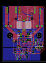
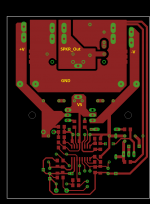
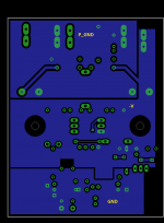
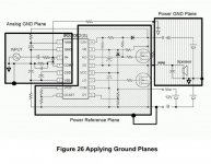
I'm trying to apply ground planes correctly. I saw Luka´s pcb and ir app note.
The board is based on iraudamp7.
What do think about this layout ?
regards!
I'm trying to apply ground planes correctly. I saw Luka´s pcb and ir app note.
The board is based on iraudamp7.
What do think about this layout ?
regards!
Attachments
Last edited:
Are you not using a heatsink ?
Are the inductor wire holes big enough ?
The layout looks about as tight as you can get it.
-The heatsink will be under the pcb.
-The inductor wire hole match correctly.
-I want to get a small pcb
------------------------------------------
But what do you think about layout?? I have no experience wiring Class D amps
regards!
This looks good, I don't think you need those diodes, above inductor... you do have them in fets if they would be needed: In fact only diodes in some app are somewhere around IRS, those you might want to add
I think you are ready to build it
Ty luka!!
I'm working on it

where can I see your irs2092 pcb assembled??
regards!
I don't think I posted it yet, not that I would remember.Ty luka!!
I'm working on it
where can I see your irs2092 pcb assembled??
regards!
Status is, both channels are working, you could say I am testing it from time to time. One still need to be updated (1st one) to be able to get higher sw. freq. and I think I will add filter from one of the IR app notes, to lower some noise. And still unsure, if I would stay on current inductors or not, they are t106-2
I don't think I posted it yet, not that I would remember.
Status is, both channels are working, you could say I am testing it from time to time. One still need to be updated (1st one) to be able to get higher sw. freq. and I think I will add filter from one of the IR app notes, to lower some noise. And still unsure, if I would stay on current inductors or not, they are t106-2
Ohh That's why i couldn't find it xD.Thanks again!
regards!

I don't know what would be the highest voltage I would go for, +/-70 to 75v is what I have, I guess around here, this should give well over 400w into 4R, which is already far too much for home use. But I think single core won't be enough with such high voltages. But you can stack them, so you have 2 cores for one inductor.
I have luch and I didn't have to buy the cores, but for such cores you should contact
Micrometals - Iron Powder Cores
and try to see, where you could get them, maybe even as samples
I have luch and I didn't have to buy the cores, but for such cores you should contact
Micrometals - Iron Powder Cores
and try to see, where you could get them, maybe even as samples
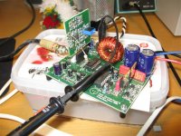
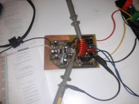
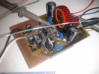
This is the pcb working at 80% ,
I have to improve the OCP,the IC enters to protect mode at high volume and select the inductor output.
No more heating. The mosfets are a bit warm.
Working at +-35vdc@450KHz , 6 ohms Load
, I have to improve the OCP,the IC enters to protect mode at high volume and select the inductor output.
No more heating. The mosfets are a bit warm.
Working at +-35vdc@450KHz , 6 ohms Load
Attachments
Hi
Does the IRFB4020 could be suitable to get 350W@8ohms ?
ty!
----------------------------------------
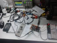
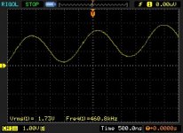
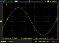
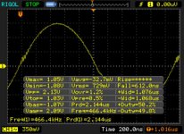
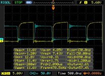
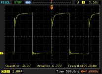
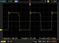
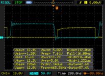
Some pictures of my amp working,I'm getting around 150W,4ohms Load,+-37vdc ,Fosc 450KHz.
Does the IRFB4020 could be suitable to get 350W@8ohms ?
ty!
----------------------------------------
Some pictures of my amp working,I'm getting around 150W,4ohms Load,+-37vdc ,Fosc 450KHz.
Attachments
-
 output_sign_carrier_clip.jpg27.6 KB · Views: 78
 -
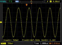 output_carrier.jpg44.2 KB · Views: 78
 -
 output_10uH_.jpg38.4 KB · Views: 77
 -
 output_.jpg51.5 KB · Views: 74
 -
 out.jpg26.5 KB · Views: 66
 -
 nice_g_signals.jpg28.3 KB · Views: 68
 -
 lo_g_com.jpg21.7 KB · Views: 374
 -
 hi_g_com.jpg21.3 KB · Views: 387
 -
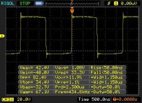
 gate_signals_com.jpg52 KB · Views: 406
 -
 irs2092 irfb4212 amp close.jpg401.2 KB · Views: 152
Last edited:
- Status
- This old topic is closed. If you want to reopen this topic, contact a moderator using the "Report Post" button.
- Home
- Amplifiers
- Class D
- Irs2092