We use the IRS20957 with IRFB4227 and also the Infineon IPP320N20NG3 with 2+2 output devices...
I use higher value gate resistors (Up to 33 ohm) to lower EMI. The higher values cause no extra dissipation in the MOSFETs in practical terms.
Steve, what were your gate rise times with the 33R resistors?
Hi Steve,
Thank you for your suggestions.
I'm assuming the catch diode is placed in series with the 10 ohm resistor? When you say -Vcc I'm assuming here that you mean Vcc and not COM (B-)?
Your totem pole configuration is very interesting and is something I will investigate. The extra cost would be two additional totem poles per channel, but would also elminate the need for turn-off diodes across Rg.
I'm wondering if the suggestion to use a much larger Rg of 33r, maximum deadtime, and running at 350kHz are all efforts to minimize dissipation and EMI or if they will also help with reliability? When I originally tried 10r for Rg instead of 4r7, I noticed a sizeable increase in THD as power levels neared clipping. I'm all for a robust design, but I'll need to weight the tradeoff against fidelity.
Finally, my understanding from comments from Eva and others in these forums, is that modern devices such as IRFB4227/4127 have internal diodes that can easily withstand high Vds/Id conditions and do not require external Schottky's. I'm guessing you do not feel this to be the case?
Thanks again!
Dear Ungie,
We use the IRS20957 with IRFB4227 and also the Infineon IPP320N20NG3 with 2+2 output devices.
Between pin 13 (IRS20957 and IRS2092) insert a 10 ohm resistor with a catch diode from pin 13 to -Vcc (We use 35nsec 1A 600v diode ES!J) This will prevent damage to the IC from any spikes which may "float" around.
I use a Totem driver per MOSFET so that the PNP can discharge directly to the source pin of the MOSFET.
In addition I do not lay out the totems like you have. The NPN has the gate charge resistor in its emitter and the PNP has its emitter directly connected to the gate of the MOSFET for super quick discharge.
I use higher value gate resistors (Up to 33 ohm) to lower EMI. The higher values cause no extra dissipation in the MOSFETs in practical terms.
The active discharge PNP takes care of a lot of issues.
Run the IR chip at max deadtime.
Run the oscillator at 350KHz
You may want to also try external Schottky diodes across the MOSFETs as their internal diode will be having a hard time at these rail voltages.
Steve Mantz
Zed Audio Corp.
Hi Steve,
is that modern devices such as IRFB4227/4127 have internal diodes that can easily withstand high Vds/Id conditions and do not require external Schottky's. I'm guessing you do not feel this to be the case?
Thanks again!
I found I got good results with a pair of IRFB4227's.
The RDSon is very low and the 2092 will drive one pair OK.
Two pairs requires a buffer IC.
An external SMD schottky diode (laid out for minimum inductance) in parallel with internal body diode (and lead inductance) actually helps to reduce the voltage spike that happens when body diode starts conducting due to forward recovery and lead inductance. This reduces the chances of avalanche in MOSFET, driver IC and diodes when operating them close to their maximum Vds/Vr. IRFB4227 are proving reliable at >190V (insane power!)
Thanks Eva,
What kind of Io rating would be required here? The specification for the IRFB4227 body diode maximum Is is 65A.
What kind of Io rating would be required here? The specification for the IRFB4227 body diode maximum Is is 65A.
An external SMD schottky diode (laid out for minimum inductance) in parallel with internal body diode (and lead inductance) actually helps to reduce the voltage spike that happens when body diode starts conducting due to forward recovery and lead inductance. This reduces the chances of avalanche in MOSFET, driver IC and diodes when operating them close to their maximum Vds/Vr. IRFB4227 are proving reliable at >190V (insane power!)
Check for I-squared-t for fusing only, as the periods of schottky conduction are going to be short (intil Rdson times Id exceeds forward drop, which wouldn't be any good anyway)
Good manufacturers do specify I-sqaured-t.
I don't see this specification anywhere on the IRFB4227 datasheet. Is it possible it's referred to as something else?
Thanks!
Bumping this thread!
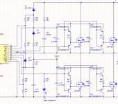
Steve, I am experimenting with your totem configuration and have added the 10r resistor and catch diode. What power rating do you suggest for the resistor? Any comments on the revised schematic?
Thanks!
Steve, I am experimenting with your totem configuration and have added the 10r resistor and catch diode. What power rating do you suggest for the resistor? Any comments on the revised schematic?
Thanks!
Dear Ungie,
We use the IRS20957 with IRFB4227 and also the Infineon IPP320N20NG3 with 2+2 output devices.
Between pin 13 (IRS20957 and IRS2092) insert a 10 ohm resistor with a catch diode from pin 13 to -Vcc (We use 35nsec 1A 600v diode ES!J) This will prevent damage to the IC from any spikes which may "float" around.
I use a Totem driver per MOSFET so that the PNP can discharge directly to the source pin of the MOSFET.
In addition I do not lay out the totems like you have. The NPN has the gate charge resistor in its emitter and the PNP has its emitter directly connected to the gate of the MOSFET for super quick discharge.
I use higher value gate resistors (Up to 33 ohm) to lower EMI. The higher values cause no extra dissipation in the MOSFETs in practical terms.
The active discharge PNP takes care of a lot of issues.
Run the IR chip at max deadtime.
Run the oscillator at 350KHz
You may want to also try external Schottky diodes across the MOSFETs as their internal diode will be having a hard time at these rail voltages.
Steve Mantz
Zed Audio Corp.
Attachments
I have a second version of this amp built up and I have encountered some strange behaviour. When the the CSD pin goes high and the output stage begins switching, there is an approximately -3v DC offset at the output which normalizes to 0V after a second or two. Obviously this causes a pop through the speaker. The IRS2092 datasheet suggests that no adjustment for DC offset is required. I have checked all startup voltages and everything looks correct (Vcc, Vbs, B+, B-, etc.). Any ideas what might be causing this to happen?
Thanks!
Thanks!
and what do you have different then in app note? on my two, I have no pop poop at all
This is a high power version with +/-90V rails, totem pole gate drive to two pairs of IRFB4227. I had earlier built a sample based on iraudamp7s on +/-50V rails which did not exhibit this behaviour.
This is a high power version with +/-90V rails, totem pole gate drive to two pairs of IRFB4227. I had earlier built a sample based on iraudamp7s on +/-50V rails which did not exhibit this behaviour.
I use a very similar set up, 4 irfb4227's with 4420 driver chips.
Sometimes it clicks or screeches and on others it is silent. I found it varies from one 2092 to another, one will show the problem and the next wont.
Idle losses depend a lot on whether the parasitic capacitances are charged passively by output inductor (resonant operation) or actively by the own output MOSFET. Resonant idle operation requires low enough output inductance, slight dead time, and not too low gate resistor (or too high gate drive voltage) to avoid forcing much higher dv/dt than the current from the inductor charging parasitic capacitances can provide.
Thank you Eva,
The original part of this thread is pretty old now, and I managed to solve the high idle losses.
I also found that the DC offset I was seeing at the start of switching was due to switching the speaker load with an output relay. With the output of the amp directly loaded by a speaker there is no offset when switching begins. I simply increased turn on time of the relay to prevent any pop from the speaker.
Now, however, I have a much bigger issue. The OCP protection of the IRS2092 is NOT working at all. Even if I set the trip thresholds as low as they will go, the protection does not trigger when the output is shorted while driving a 4ohm load at 1W or 10W. This design is close to the iraudamp9, except that I am using a totem pole driver for each mosfet and I don't have the 10k resistors from gates to VS (HS) or gates to B- (LS). Other than that the designs are similar. I have read many discussions with OCP triggering randomly, but in my case it's not working at all. Is the gate drive buffer causing an issue here? IR does a lot of hand waving in their documentation without any discussion of OCP with gate drive buffers. I will try and speak to IR but in the meantime any ideas would be most appreciated!
I had the opposite trouble with the amp tripping far too soon.
The levels are set from the DS voltage on the MOSFETs.
You would need to pull quite a bit of current before even a low level would trip the OC.
At 2v5 into ocset and csh I could get around 200watts.
To get to 750 watts I had to up the ocset to around 4 volts to stop it tripping too soon.
The levels are set from the DS voltage on the MOSFETs.
You would need to pull quite a bit of current before even a low level would trip the OC.
At 2v5 into ocset and csh I could get around 200watts.
To get to 750 watts I had to up the ocset to around 4 volts to stop it tripping too soon.
I use a Totem driver per MOSFET so that the PNP can discharge directly to the source pin of the MOSFET.
Steve Mantz
Zed Audio Corp.
Thinking about this some more, is it not risky to have separate gate drive buffers for each MOSFET? Variations in Hfe of the buffer transistors could result in slightly different switching times between the paralleled output devices. Or is matching the transistors for Hfe a requirement?
Thinking about this some more, is it not risky to have separate gate drive buffers for each MOSFET? Variations in Hfe of the buffer transistors could result in slightly different switching times between the paralleled output devices. Or is matching the transistors for Hfe a requirement?
I use tc4420 gate drivers that have matched on/off times.
- Status
- This old topic is closed. If you want to reopen this topic, contact a moderator using the "Report Post" button.
- Home
- Amplifiers
- Class D
- IRS2092 High Power mosfet heat question