Well, I've rearrenged all the 3 pairs of amps acording to the schematic and the hum did decrease... but it's still there  and sometimes I turn it on and there's a loud hum, then I turn it off and the next time I turn it on the loud hum has disappeared :S
There is now a hissing sound that persists when power is turned off until the preamp's supply caps are drained, so I'm guessing there is now a problem with the preamp's ground layout right?
I'll post the schematic when I have the time to draw it... it's quite complex!
Thanks for all the help so far
and sometimes I turn it on and there's a loud hum, then I turn it off and the next time I turn it on the loud hum has disappeared :S There is now a hissing sound that persists when power is turned off until the preamp's supply caps are drained, so I'm guessing there is now a problem with the preamp's ground layout right?
I'll post the schematic when I have the time to draw it... it's quite complex!
Thanks for all the help so far
Devius, from your schematic I understand that you use a CT trafo.
You could optimize the whole amp much better using a trafo with independent secondaries.
That way, the grounds are formed at the (double) bridges and you have independent grounds for each pair of channels.
I think that to eliminate the noise on a 6-channel amp with only one trafo, this is the way.
You could optimize the whole amp much better using a trafo with independent secondaries.
That way, the grounds are formed at the (double) bridges and you have independent grounds for each pair of channels.
I think that to eliminate the noise on a 6-channel amp with only one trafo, this is the way.
Well... long time no see but still with problems, just not enough time to work on this thing. Attached is the schematic of the pre-amp since I believe that the power-amp ground layout is now correct.
With this layout there is still no hum or buzz int he phones-out but some on the amp. When I connect the pre-amp to a PC-soundcard there is a LOT of noise present. I mean, there is noise even when the pc is idle, but just by moving the mouse the noise increases a lot!
Can anyone please tell me if this layout is incorrect?
PS: the RGND is the relay ground
Attachments
Update:
There seems to be some kind of ground energy in the ground traces or something like that since now I get a quite audible buzz upon turning on the equipment with nothing connected to the input, but when the ground connector of a plug is inserted in the input the buzz decreases quite a bit. Also, the buzz increases with the volume pot and is also present on the headphones out although not so audible. Also, due to the muting feature of the headphone out, the buzz isn't present on the speakers when phones are connected. So, maybe there is some problem in between the two parts of the pre-amp. Any sugestions?
There seems to be some kind of ground energy in the ground traces or something like that since now I get a quite audible buzz upon turning on the equipment with nothing connected to the input, but when the ground connector of a plug is inserted in the input the buzz decreases quite a bit. Also, the buzz increases with the volume pot and is also present on the headphones out although not so audible. Also, due to the muting feature of the headphone out, the buzz isn't present on the speakers when phones are connected. So, maybe there is some problem in between the two parts of the pre-amp. Any sugestions?
After a LONG time I've had another go with it.
I changed all the wiring - twisted the +V/-V and GND wires from the PSU to each amp very tightly. Also, the PSU is now Transformer -> Bridge Rectifier -> Two filter banks (One +V and another -V) with 15400uF each for all the amps.
This arrangement gives zero noise without an input connected. As soon as I connect something, no matter what, even not passing through the pre-amp, there is buzz at the output. And quite audible.
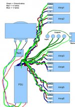
During the testing I found some curious aspects. First, with the input ground connected to the star ground there is almost no noise (I have to put my head against the speaker to ear it and even still it's quite low) in amps 5 and 6 of the attached picture. However, that arrangement gives a louder buzz in amps 1,2,3 and 4 compared to the layout in the picture. To reduce buzz in those amps I have to connect the input ground directly to one of the ground traces of the amp's board. Doesn't matter which one as long as it's one of the pair that share the heatsink. This is quite strange as there is no interaction between the boards in the pair except at the star ground. The only difference between amps 1,2,3, 4 and 5,6 is that the last two don't have the 100pF cap in parallel to the feedback resistor. Besides the different physical disposition.
Remember I'm using a wooden box and the only part that can be considered "chassis" are the heatsinks.
Any ideas??
I changed all the wiring - twisted the +V/-V and GND wires from the PSU to each amp very tightly. Also, the PSU is now Transformer -> Bridge Rectifier -> Two filter banks (One +V and another -V) with 15400uF each for all the amps.
This arrangement gives zero noise without an input connected. As soon as I connect something, no matter what, even not passing through the pre-amp, there is buzz at the output. And quite audible.
During the testing I found some curious aspects. First, with the input ground connected to the star ground there is almost no noise (I have to put my head against the speaker to ear it and even still it's quite low) in amps 5 and 6 of the attached picture. However, that arrangement gives a louder buzz in amps 1,2,3 and 4 compared to the layout in the picture. To reduce buzz in those amps I have to connect the input ground directly to one of the ground traces of the amp's board. Doesn't matter which one as long as it's one of the pair that share the heatsink. This is quite strange as there is no interaction between the boards in the pair except at the star ground. The only difference between amps 1,2,3, 4 and 5,6 is that the last two don't have the 100pF cap in parallel to the feedback resistor. Besides the different physical disposition.
Remember I'm using a wooden box and the only part that can be considered "chassis" are the heatsinks.
Any ideas??
Attachments
OK couple of questions...
1. do you have a ground connection to your heatsink?? if you don't try running one back to the mains earth point.
2. have you tried putting the 100pf cap across the feedback resistor in the other amps? This will give you unity gain at radio frequencies and above, stopping the amp from oscillating ultrasonically... could be that when you move the signal ground to the star point the amps without the 100pf are oscillating, which can be a cause of buzzing.
If the heatsinks aren't connected to earth try grounding them first (assuming you are using isolated chips or suitable insulating washers!), as non grounded heatsinks can cause oscillations.
Tony.
edit: note that the comment on heatsink grounding is from my experience with solid state amps... I don't know whether it is as important with chip amps, but worth trying
Thanks for the reply but you misunderstood or misread my post. As I said, the heatsinks are earthed and the amps that DO buzz are the ones that HAVE the 100pF caps in parallel with the feedback resistor. This will be the first thing I'll test this afternoon. If it doesn't work, I'll try connecting the signal ground and the mais earth ground in other ways. I already did this, but not with all 6 amps connected at the same time.
And to answer your question about grouding heatsinks with chipamps, it is also necessary. I found that all 6 amps produced a slight buzz (audible at about 30cm from the speakers) when the heatsink was not connected to ground. This, of course, with no input connected.
And to answer your question about grouding heatsinks with chipamps, it is also necessary. I found that all 6 amps produced a slight buzz (audible at about 30cm from the speakers) when the heatsink was not connected to ground. This, of course, with no input connected.
No problem!! I actually apreciate the reply.
Current status:
Amps 3,4,5 and 6 are quiet with and without input connected. How? Disconnected the safety earth from the circuit and connected the signal input ground to the star point. Amps 1 and 2 still hum and it's not neglectable. Don't worry, I'll try connecting the safety earth to other points in the circuit to find a point where it doens't impact performance. If there is no such point I'll just install a loop breaker.
My guess is that the hum in amps 1 and 2 comes from some sort of input coupling. If I connect the signal directly to the amps board there is no hum at all. But connecting it to the input plug produces hum. Maybe it's the proximity to the tranformer and some large current loop area that's responsible. I'll try to reduce wire's length and use some thicker wire in the +/-V and ground connections to the psu to see if it helps.
For anyone interested in building multi-channel amps:
One advice for future reference. If you're planning to build a multi-channel amp and you're new to electronics use these design guidelines:
- For each transformer also use just one bridge (or the double bridge typology) and one set of filter banks (one +V and one -V)
- Use a star point grounding
- Connect all ground returns to the star point. If it's not on the psu, connect speaker return grounds to the psu ground, where power leaves the board then connect a wire to the star point. Also always connect the ground wire comming from the amp's board to the psu ground and not the star point if it's not on the psu itself
- Use a big case to keep the layout as symmetrical as possible. All wires with the same function should have the same length preferably. The big case also helps in keeping a distance from the transformer
- Try to keep all wires as short as possibel
- Twist the +V/-V and ground wires going from the PSU to the amps together as tightly as you can
- Use separate input plugs for each amp. That way you can test several points for connecting the individual input grounds for each channel to achieve the lowest possible noise
These are all things I didn't do in the first place and the result was buzzing and humming all over the place and very difficult to eliminate. If something is incorrect or missing please do correct me.
Devius said:But connecting it to the input plug produces hum. Maybe it's the proximity to the tranformer
I suspect that you are correct. With standard RCA's the sheilding is broken at the socket, whereas if you run direct to the board, the sheild is intact until almost the final connection point. As a sanity check, you could temporarily move the transformer out of the case and run some longer wires to your switch and bridge, if the hum dissapears in channels one and two, the chances are it is radiated noise and probably the only course of action will be some sort of sheilding...
Tony.
you could temporarily move the transformer out of the case
Well, that would be a thing to test for sure, but I simply don't have enough space to install a shield in there. It is all a bit cramped, specially the inputs, outputs and the transformer. That's the worst part of the whole design! But I'm only fixing it. Doing it all over again is completely out of the question. Anyway I guess I'll try to take the transformer out of there if I can't find a solution for amps 1 and 2 tomorrow. Another thing to look for is the radiation patern of a E-I transformer. Maybe that way I can do an optimal shield.
Another bad aspect of my design is the input connector. It's a 7 contact + shield type of plug, so I only get one input ground wire. As all the other problems it's a direct result of trying to use a too small case.
Only now I'm beggining to understand the whole loop area business.
ahhh that was something else I was wondering about, but I wasn't sure that it would be part of the problem, especially after the info in your latest post. (that is whether you had a separate input signal ground for each amp/channel running back to your star point).
yes knowing the radiation pattern would probably help (if that is the culprit) is the chassis so tight that you can't even re-orient the transformer (ie turn it on it's axis) if that would help?
at least if you do the test and the hum goes, you can be pretty sure that any other changes to your grounding are not going to help, and it narrows down what remedies you need to try
Tony.
Well today I found out that a transformer can generate a lot of noise! I removed the transformer from the case and ran some wires back to the circuit and the source of the buzz was found. The amps were very quiet with the transformer far away. Not exactly silence but a huge improvement over the previous case.
Amps 3,4,5 and 6 aren't all that quiet with the transformer in the case. I guess I wasn't paying that much atention yesterday. And I hadn't removed the safety earth at all. I forgot there was a wire under all the others going from the IEC mains plug to the star point.
Now I need an easy way of shielding a transformer in a box with almost no room to spare... :\ I also tried the transformer in several positions to see if it helps but with no positive results.
So I did a shield and it helped a little bit, but still not good enough. The shield is made of a piece of metal taken from the underside of an old keyboard. It covers three sides of the transformer, those that are facing the innere side of the box, and the top.
Channels 3,4 are now as quiet as if the transformer was outside the box, the other ones aren't all that quiet. I just realized that the amount of buzz increases the longer the wires from the psu to the amps are. So, I guess my next step is to use thicker wires in there.
Would it help to also shield the side of the transformer that's opposite to any circuit? (It's the left side on the drawing I posted earlier)
Hi Devius,
I'm having a similar problem with a test amp on my workbench. (poor wiring, yes) Maybe my observations my help. I haven't found a solution yet.
Amp is reasonable quite with no input cable plugged in.
Plug input cable in (just cable) buzz increases dramatically. Different cables produce volume of buzz. Touch end of input cable increase volume.
Plug other end of cable into a 100k pot that is connected to CDROM player and buzz is still present at low volume settings but reduced somewhat. Volume of buzz seems constant at low volume settings then disappears at higher volume settings.
I would assume the buzz in being introduced in the input cable. I can't understand RF interference results in low frequency buzz. I'm wondering if the output impedence of the pot is making a difference.
I guess that the CDROM player switchmode AT PSU is the cause of the interference. Are you using a CD or DVD player with a switchmode PSU?
Regards
Hi Devius,
I'd try making those wires to amps one and two even longer.... why you ask?? to try re-routing them so that they don't pass so close to the transformer. the problem may be that the transformer is inducing noise into the PS wires. From your diagram they pass very close to the transformer.
I'm thinking this is the cause, because amps 3 and 4 are (from the diagram) about the same distance from the transformer as amps 1 and 2, and the ps wiring passing close to the transformer appears to be the main difference.
Tony.
- Status
- This old topic is closed. If you want to reopen this topic, contact a moderator using the "Report Post" button.
- Home
- Amplifiers
- Chip Amps
- Irritating buzz... where is it comming from???