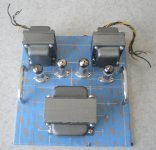
The project has been moving along, I took apart the old transformers and stripped the old paint/rust off the end bells with a wire wheel and Scotch-brite. They have been primed and painted metallic cast iron gray, a more fetching finish than the usual black. Both automotive touch-up paint and engine enamel work well for this purpose. I gave the finished end bells a bake in my oven at 200F for an hour or so to set the finish.
This afternoon, I'll be doing the same to the transformer lams (except for the bake), with the windings and wires masked off with tape.
The old, ganky-looking (they always are) screws will be replaced with stainless steel, which will blend well with the new paint job.
This afternoon, I'll be doing the same to the transformer lams (except for the bake), with the windings and wires masked off with tape.
The old, ganky-looking (they always are) screws will be replaced with stainless steel, which will blend well with the new paint job.
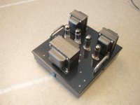
Here's a pic of the top deck in progress. I'll be removing the masking tape when all the holes are drilled (still need a few for power supply mounting. The top deck will then get some deep metallic blue auto touch-up paint. Next challenge will be hogging out the holes for the AC input module, pilot light, and input/output connectors. These will all go in the bottom pan, which willl be painted metallic cast-iron grey to match the transformers.
Attachments
Last edited:
Any decisions on screen supplies and such will be deferred until I get everything together and power it up with a set of tubes. Since the only load on the main power XFMR will be the output tubes, it may be overgenerous with B+, and I may have to tame the tiger by toning down/regulating the screens.
Another note - I've been reading some comments on garter feedback on other forums. It may be best suited for class A operation.
As a thought experiment, consider what happens when the amp is in serious class B mode, with one side in cutoff for extended periods of time. The RC circuit sampling the bias on the cut-off side will discharge and start to screw up the bias for the other side. Once this objection was stated, it was obvious in retrospect. Some people mention LF oscillation as a problem.
I selected a slow RC time constant for the current sampling networks (I could also go slower), but it may not be enough to get around the problem. If that's the case, I'll revert back to plain combination bias and figure out some other auto-balance circuit some other time. I have some nice matched quads of JJ 6BQ5s that could come to the rescue...
How attached to the Garter Bias are you? Are you making a PCB for this amp?
I have done two amps so far with active automatic bias circuits. I had an old Fisher amp that had a single common cathode resistor for the output tubes (awful idea, caused red-plating of tubes unless they were nearly perfectly matched). I replaced that resistor with individual LM317s as CCSs and bypassed those with caps. Boom, done. Ultra simple and it works much better (and no more need to manually set bias current).
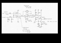
The other that I did used the Van Der Veen bias servo circuit that Guido Tent sells. The schematic is around on the net. I'll attach it here. I use this circuit in my Unity-Coupled Plitron amp and I am able to listen to very bass-heavy music at levels that rattle the windows and make my ears bleed without inducing any noticeable crossover distortion. In other words, I think that the long time constant and the clamp circuit are plenty effective enough at keeping bias drift down with loud music. This may be more complex of a solution than you are looking for though since it would require a negative rail for the bias supply in addition to the complexity of the circuit itself.
Anyway, I just thought I'd throw those out there.
I have done two amps so far with active automatic bias circuits. I had an old Fisher amp that had a single common cathode resistor for the output tubes (awful idea, caused red-plating of tubes unless they were nearly perfectly matched). I replaced that resistor with individual LM317s as CCSs and bypassed those with caps. Boom, done. Ultra simple and it works much better (and no more need to manually set bias current).
The other that I did used the Van Der Veen bias servo circuit that Guido Tent sells. The schematic is around on the net. I'll attach it here. I use this circuit in my Unity-Coupled Plitron amp and I am able to listen to very bass-heavy music at levels that rattle the windows and make my ears bleed without inducing any noticeable crossover distortion. In other words, I think that the long time constant and the clamp circuit are plenty effective enough at keeping bias drift down with loud music. This may be more complex of a solution than you are looking for though since it would require a negative rail for the bias supply in addition to the complexity of the circuit itself.
Anyway, I just thought I'd throw those out there.
Attachments
How attached to the Garter Bias are you? Are you making a PCB for this amp?
<snip>
Now it would be nice if someone could make a PCB (throughhole) for this circuit: sure it can be done on perfboard, but a PCB would be so much easier
")
Holes are all drilled/hacked in the bottom pan (I think), and I gave it it a coat of metallic cast-iron grey paint last night, to be baked tonight. I think I have the final coat of paint on the top plate. If so, I'll start assembling all the various bits this weekend. This should be a fairly spiff-looking amp - I hope the performance will be as good.
- Status
- This old topic is closed. If you want to reopen this topic, contact a moderator using the "Report Post" button.
- Home
- Amplifiers
- Tubes / Valves
- "Iron Garter" Push-Pull Amplifier