Hi Wavebourn,
If these are the diagrams to your low bias current model you were referring to, then thank you. Given your earlier comment I don't think so.
However, this has become a diversion to what JojoD was asking. I do not intend to discuss your low current version any further. You may start your own thread on this if you wish.
-Chris
anatech said:
However, this has become a diversion to what JojoD was asking.
-Chris
Hi JojoD,
was a proposal to use your transistors assuming their own essentional characteristics (instead of drop-off replacement for another devices) a diversion against what you were asking?
")
JojoD818 said:Hi guys,
I have some IRFP240/IRFP9240 leftovers from an F1 project, I was hoping I can build a simple class ab amp out of a single pair. Power output is not an issue as long as it sounds good. Any schematics would be appreciated.
Thanks!
JojoD
JojoD,
may i know where did you get your IRF's? I really need some of those.
thanks bro!
rodel
Wavebourn said:
Hi JojoD,
was a proposal to use your transistors assuming their own essentional characteristics (instead of drop-off replacement for another devices) a diversion against what you were asking?
Actually it's like a learning project, any amp will do as long as I can keep it from burning. I just wanna learn as much as I can from using this devices. Maybe have an awesome sound while I'm at it but that is the least of my expectations as I just wanna learn.
Thanks!
Re: Re: IRFP240/IRFP9240 Power amp
Hi,
in here: http://ph.farnell.com/jsp/home/homepage.jsp
care to share where you will use 'em Kabayan?
Thanks
roddeasis said:
JojoD,
may i know where did you get your IRF's? I really need some of those.
thanks bro!
rodel
Hi,
in here: http://ph.farnell.com/jsp/home/homepage.jsp
care to share where you will use 'em Kabayan?
Thanks
Have you guys tried this
http://www.tech-diy.com/hexfets.htm
They're not cheap but the site is reliable, I've ordered many times from them...
http://www.tech-diy.com/hexfets.htm
They're not cheap but the site is reliable, I've ordered many times from them...
Re: Amp with IRF240/9240
Hi RSK,
Any links for this amp?
Thanks,
JojoD
RSK said:Hello diy-ers,
I have built the white noise audio (MOS100) with the above mosfets. They sound very good. Input FET opamp.
You should try it.
Cheers.
RSK.
Hi RSK,
Any links for this amp?
Thanks,
JojoD
Re: JojoD818
RSK,
Thanks a lot!
Regards,
JojoD
RSK said:
RSK,
Thanks a lot!
Regards,
JojoD
Re: JojoD818
White Noise Audio -- http://www.wnaudio.com/
also has got a little forum at
http://www.audiocircle.com/
White Noise Audio - board
http://www.audiocircle.com/circles/index.php?board=36.0
but not much used right now, it looks
RSK said:
White Noise Audio -- http://www.wnaudio.com/
also has got a little forum at
http://www.audiocircle.com/
White Noise Audio - board
http://www.audiocircle.com/circles/index.php?board=36.0
but not much used right now, it looks
Re: Re: JojoD818
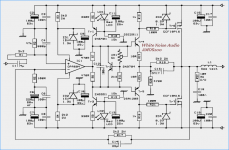
AMOS100
is using an OPA604 op-amp for input and gain control
and
two very high quality Lateral MOSFET for output.
As the output has got voltage gain of 4-5 ( common Drain Push-Pull )
the output voltage can be higher than OP-Amp can produce.
See my attachment schematic of
White Noise Audio
AMOS100
lineup
lineup said:
White Noise Audio -- http://www.wnaudio.com/
also has got a little forum at
http://www.audiocircle.com/
White Noise Audio - board
http://www.audiocircle.com/circles/index.php?board=36.0
but not much used right now, it looks
AMOS100
is using an OPA604 op-amp for input and gain control
and
two very high quality Lateral MOSFET for output.
As the output has got voltage gain of 4-5 ( common Drain Push-Pull )
the output voltage can be higher than OP-Amp can produce.
See my attachment schematic of
White Noise Audio
AMOS100
lineup
Attachments
JojoD818 said:lineup,
Wasn't it mentioned somewhere that Lateral mosfets cannot be substituted with hex? But RSK was able to build it with hexfets so no problem there. Do you mean opamp has not enough voltage swing?
In some amp circuits IRF HEXFET can be used instead of Lateral
without any danger.
This is has been explained in detail in previous postings in this topic.
By me as well as other posters.
Also is many other threads at this forum with such warnings to use HEXFET in some circuits.
=====================================
If we focus on AMOS100.
Schematic in my last post here above.
This circuit uses Tr2, a VBE-multiplier, to control the idle current in driver stage.
Tr2 should be place onto heatsink to sense the temperature.
When heatsink gets too HOT, then Tr2 will reduce the current in Tr4 + Tr5.
But this case control is NOT directly to the output MOSFET.
It only controls current level in Tr4 + Tr5 = the drivers.
But the drivers current will effect MOSFET, by changing voltage across R13 and R16.
I would say this AMOS100 is a borderline case.
It might work with HEXFET,
but best is of course to use same Lateral MOSFET as in circuit.
Because this is what it was designed for!
I would, to avoid problems, build AMOS100 exactly as is intended.
And careful read and follow instructions in the good documentation PDF.
-----------------
Generally Op-amps have a recommended max supply around +-15 to 18 Volt,
so this means that most op-amps will not be able to produce
an AC output voltage more than like +-15 Volt peak.
In AMOS100, OPA604 is supplied with +-15 volt, set by ZENERS ZD1 and ZD2.
So an output like 8-9 Volt RMS would be maximum, from OP.
But because the 4 transistors at output has got a voltage gain of
like 4-5, set by (R19+R20)/R20,
the total max output voltage of AMOS100 will be well up to deliver 100 Watt RMS.
** 8V RMS into 8 Ohm would give 8 Watt.
------------------
Advice:
You may try to use AMOS100 circuit using HEXFET like IRF240, IRF9240,
and there is a chance they may work.
Most probably for best result, even if they work, you would have to modify output stage a bit.
To fit HEXFET better.
But my advice would be to try and find
An Amplifier Circuit, that was originally designed for HEXFET use
and even best if using IRF240-IRF9240 or very similar transistors
as standard devices, from the beginning.
regards
lineup
Wow, quite a thread considering it started with a simple question about some IRF devices.
Just today I listed to my audio system for a couple hours which includes an ADCOM GFA-5500 power amp. It's a great sounding, powerful, dependable amp that uses IRF9240 and IRF240 output devices. And, it also happens to have been designed (mostly, anyway) by Mr. Pass.
So, I'd say yes, those devices can be used to build a good sounding amp without too much difficulty. While my GFA-5500 is not a simple design, it's not very complex either. I have the schematics and they're pretty cool, unfortunately I can't post them for reasons already mentioned.
So, before you get talked out of using the IRF devices by people who practice audio-sorcery, I’d locate a few amp designs from this forum, pick one that’s reasonably based on science and within your capabilities, and build it. It feels good to build something, is fun when it works (if it works : ), you’ll likely learn something new, and it will probably sound decent. You can’t listen to schematics and forum threads.
- Status
- This old topic is closed. If you want to reopen this topic, contact a moderator using the "Report Post" button.
- Home
- Amplifiers
- Solid State
- IRFP240/IRFP9240 Power amp