Hi,
I have posted a IRF540/IRF9540 amp, that uses a new idea of employing current mirrors to use both legs of the diff-pair to drive the VA-stage. Should be here somewhere under a topic named 'new idea' or something like that. It is designed to actually work.. If i'm recall correctly, I once posted a IRF540/IRF9540 disign is a topic called 'cheapest amp possible' or somthing like that....that one should also work..
cheers,
Thijs
Lars Clausen said:Has anyone seen any examples of real life IRF 540/9540 amplifiers here on DIYaudio.com? (apart from the ULCA).
I mean amplifiers that are designed to actually work.
Check this page: http://users.otenet.gr/~athsam/#Audio_Power
There are two amplifiers with IRF540/9540
sajti
Lars Clausen said:Has anyone seen any examples of real life IRF 540/9540 amplifiers here on DIYaudio.com? (apart from the ULCA).
I mean amplifiers that are designed to actually work.
Hey lars we did never see the finished amp i guess it was the .. ULCA2 ...
~3 * 3cm.. ??
")
what with this ??
Your output devices have long been obsolete. Don't buy these transistors, you will get fakes. The diode string is the wrong way round.
I have a very simple amplifier for you, which is made from "real" transistors and a opamp input stage. It is a proven, reliable design. It can be scaled up and down as you like...
Click here
SonnyA: You have a really good memory The project is not forgotten, it was the idea of making a good amplifier kit at a really low price. Was the proposed price range some 10$ per ch. in parts?
Now some work has been done with this idea over the past 6 months, and about to overcome the obsticles of high capacitance in the MOSFET's vs. the quest for higher bandwidth. The new idea in the bowl of this project is that you can't successfully forget high performance in the search for low cost. Even if some low cost / low performance solutions has made it over the years.
But why not try to make something better?
The performance has to be there first, and then if the price is reasonable, i think the project has sustainability. That is why the ULCA project is changing into 'high speed / high performance MOSFET amplifier' project instead. Not with so much focus on ULC (Ultra Low Cost), but instead high performance using these incredibly rugged and potentially fast IRF output devices.
To get open and airy reproduction of treble, the ULCA is now turning into a 'ultra wide bandwidth' amplifier combining some of the features described in the ULCA thread. Bandwidth as high as 500.000 Hz (-3dB) is now possible, and fully stable.
Also i think limiting the output power to 50W/100W of the small output devices, is a drawback, so the circuit and PCB in it's new version also allows for use of bigger output devices. Power of 100W/200W is now very easy.
Of course the size of the PCB is now slightly bigger, and also the price also higher than the 10$ per ch. first proposed.
I know to get really high power in a small space, and the highest quality, there is today (IMHO) no way to get around PWM. The state of the art is Class D. But analog amplifiers can still have a place, as they are simple, cheap and fun to play with. And still can give you great performance, at the cost of potent power supplies and nice big heat sinks.
ULCA
The project is not forgotten, it was the idea of making a good amplifier kit at a really low price. Was the proposed price range some 10$ per ch. in parts?Now some work has been done with this idea over the past 6 months, and about to overcome the obsticles of high capacitance in the MOSFET's vs. the quest for higher bandwidth. The new idea in the bowl of this project is that you can't successfully forget high performance in the search for low cost. Even if some low cost / low performance solutions has made it over the years.
But why not try to make something better?
The performance has to be there first, and then if the price is reasonable, i think the project has sustainability. That is why the ULCA project is changing into 'high speed / high performance MOSFET amplifier' project instead. Not with so much focus on ULC (Ultra Low Cost), but instead high performance using these incredibly rugged and potentially fast IRF output devices.
To get open and airy reproduction of treble, the ULCA is now turning into a 'ultra wide bandwidth' amplifier combining some of the features described in the ULCA thread. Bandwidth as high as 500.000 Hz (-3dB) is now possible, and fully stable.
Also i think limiting the output power to 50W/100W of the small output devices, is a drawback, so the circuit and PCB in it's new version also allows for use of bigger output devices. Power of 100W/200W is now very easy.
Of course the size of the PCB is now slightly bigger, and also the price also higher than the 10$ per ch. first proposed.
I know to get really high power in a small space, and the highest quality, there is today (IMHO) no way to get around PWM. The state of the art is Class D. But analog amplifiers can still have a place, as they are simple, cheap and fun to play with. And still can give you great performance, at the cost of potent power supplies and nice big heat sinks.
ULCA
Nice to hear lars.
Maybe we should meet/or talk in the phone..
I agree with you that if we want a good performance we need a little more. But still it should be possible to make a "VW beetle" amp for everyone at resonable price with a good performance...
Maybe not look so much on what is "latin" regarding parts to use. But design an amp with the right parts to get the right performance..
Maybe it should be more like a 3 - 400DKK per channel amp?
Maybe make a joint design?
The problem with the IRF540 is the relatively high gate drive voltage required at high output currents. You need a gate drive supply 8V beyond the supply rails. Or you end up with an inefficiently used power supply i.e +/-40V supplies to get a +/-30V output swing.
The classic way around this problem is bootstrapping the drive voltage. I have only seen it done to the upper transistor. If you are using a complementary N/P channel pair you need to bootstrap both power MOSFETs.
Here is the BBW amp. Bootstrap Both Ways. Its cousin the ambiamp swings both ways! Its not as good as the blameless but probably better than the gainclone because of the output stage symmetry. It is based on the 1977 Hitachi application note. I have not got around to building it but it simulates OK
Attachments
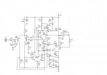
It's realy prehistory of mosfet amp. Why do you see problem with higher rail voltage for driving of mosfets gates ? Use two low voltage ( you have truth, it must be practicaly about 7 - 8 V higher ), low power supply, connected in series with main supply. All cost approximately 3 - 4 pound for one channel. Is eight pound problem for you ?
consort: I would be a little bit worried about that 1N4007 in the gate of the upper MOSFET. If you go to higher frequencies, the turnoff time of this diode is so slow that it might cause high order distortion and increased BIAS current. Why not put the Vg limiter from G to S instead? Did you mod this schematic from Hitachi? I am reluctant to believe they would use IR fet's
Upupa: I think that you give a good suggestion. Your solution is a clean and effective way to increase the power of the output stage, the bad news, it ALSO has a tendency of doubling the complexity of the power supply.
BTW when ever you use a small mains transformer together with a large one: ALWAYS use a separate small fuse for the small transformer (if you want to counteract the risk of fire...) .
.
All the best from (finally) SUNNY Denmark
If you go to higher frequencies, the turnoff time of this diode is so slow that it might cause high order distortion and increased BIAS current. Why not put the Vg limiter from G to S instead? Did you mod this schematic from Hitachi? I am reluctant to believe they would use IR fet's Upupa: I think that you give a good suggestion. Your solution is a clean and effective way to increase the power of the output stage, the bad news, it ALSO has a tendency of doubling the complexity of the power supply.
BTW when ever you use a small mains transformer together with a large one: ALWAYS use a separate small fuse for the small transformer (if you want to counteract the risk of fire...)
. All the best from (finally) SUNNY Denmark
Richie00boy: When you add the gain, you want to use resistors of fairly high value, to keep the losses low in these resistors. If you were to use like 100 Ohms, you would spill several Watts in these resistors at say 100 W output power.
That's why i added the extra transistors so you can run everything at a nice low current
But still this stage has the usual drawbacks of a CFP output stage, as the idle current grows with high frequency. So it's not recommendable for frequencies above say 50 kHz. OK for PA though.
That's why i added the extra transistors so you can run everything at a nice low current
But still this stage has the usual drawbacks of a CFP output stage, as the idle current grows with high frequency. So it's not recommendable for frequencies above say 50 kHz. OK for PA though.
I prefer the term venerable rather than prehistoric for the amp
Maplin sold a 150W kit based on the original until recently.
I got the idea of using IRF type Mosfets from Dr David White's article in Electronics World Aug 2001. He suggested various improvements which enhance but complicate the design. The bias generator is borrowed from his design. I forgot to put a 470 ohm pot in series with R9 to set the quiescent current to 100mA. My simulator does not like pots.
I think the idea here is a cheap "junk box special" design. You can now buy low gate voltage FETs which would take away the need for bootstrapping.
consort_ee_um: Only shows another limitation of a simulator as opposed to doing 'the real thing'.
Low Vgs FET's are only like 2V lower than the normal ones, You still lose significant amounts of peak voltage with these devices.
Another thing is that it also seems you would be limiting yourself to TO220 pack's (and smaller)??
All the best....
Lars
Low Vgs FET's are only like 2V lower than the normal ones, You still lose significant amounts of peak voltage with these devices.
Another thing is that it also seems you would be limiting yourself to TO220 pack's (and smaller)??
All the best....
Lars
Rejeev Luthra: I agree completely
It's only a shame the IR only make two different usable sets IRFP140/9140 and IRFP240/9240. However both these sets (depending on your choice of speaker impedance) will produce up to about 250 Watts of good clean audio power with no spec violations.
IR: A P-channel option for IRFP360 would be nice thankyou-very- much ....
Lars
btw. You can overcome the small-package-problem by mounting it directly on a solid copper block of 2 by 2 by 1 cm, without insulator between TO-220 and block (only compound), and instead insulation between block and heatsink. This way you can dissipate as much power in a TO-220 as a TO-247. It is not a very cost effective solution tho.....
It's only a shame the IR only make two different usable sets IRFP140/9140 and IRFP240/9240. However both these sets (depending on your choice of speaker impedance) will produce up to about 250 Watts of good clean audio power with no spec violations.
IR: A P-channel option for IRFP360 would be nice
thankyou-very- much ....Lars
btw. You can overcome the small-package-problem by mounting it directly on a solid copper block of 2 by 2 by 1 cm, without insulator between TO-220 and block (only compound), and instead insulation between block and heatsink. This way you can dissipate as much power in a TO-220 as a TO-247. It is not a very cost effective solution tho.....
- Status
- This old topic is closed. If you want to reopen this topic, contact a moderator using the "Report Post" button.
- Home
- Amplifiers
- Solid State
- Irf540 Amplifier