Hi everyone,
Nrik is right, that's a quasi complementary topology with vertical MOSFETs, generally, quasi complementary topologies are used, when the N-type device don't a have a similar P-type device, because generally the N-type shows better transconductance characteristics compared to the P-type. This topology has some drawbacks because it needs an auxilliar transistor to bias the lower side transistor, because Vgs (or Vbe) is referenced to Vss or Vee, instead of the output which is close to ground on quiescent state. This auxilliary transistor causes assymetrical loading on the VAS, and can lead to increased distortion, and some instabilities, so there are some ways to avoid this problems such as the Baxandall diode improvement, and sometimes, IPS to output compensation networks are necessary, because an emitter/source follower could have gain and can lead to some instabilities. Actually almost all known audio hybrid ICs (such as LM1875, LM4765, TDA7294, some old STKs, ...) uses this topology.
Thank you very much for your attention,
Best regards,
Daniel Almeida
Quasi started a number of Threads dedicated to using quasi complementary output stages.
Worth going back and reading them (if you want to!). There is a lot to learn. Some (maybe a few) designers claim that a properly designed quasi stage will sound better than a complementary stage where the N&P complements are poor matches. This may be true since very few output transistors are available as true complements.
Worth going back and reading them (if you want to!). There is a lot to learn. Some (maybe a few) designers claim that a properly designed quasi stage will sound better than a complementary stage where the N&P complements are poor matches. This may be true since very few output transistors are available as true complements.
Your Circlophone amplifier with N mosfet outputs is another good one.
http://www.diyaudio.com/forums/soli...ssories-beginner-friendly-23.html#post3459051
Yes, but the CircloMos has the advantage of being able to swing almost to the positive rail.Your Circlophone amplifier with N mosfet outputs is another good one.
I think there is a confusion about the denomination "quasi": as the name implies, it is quasi-complementary, which implies that the topology is the same as any complementary OP, but with one of the transistor being a CFP simulating an opposite sex transistor.
There is at least one other variety, the one used in the Circlophone and CircloMos, which I name "Circlo", because the load, output transistors and supplies can be rearranged in any order, including Circlotron
Hi everyone,
It's possible to add a protection system, or it's very complicated, or there's not enough room available?
I've never repaired a car amp.
That's weird a car audio amp without S/C protection.
IRFPs are a bit expensive, if it's possible, you should try to add a protection system, in this post I've attached some Michael Kiwanuka's protection schemes.
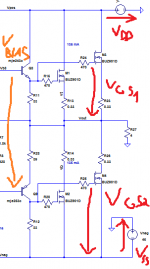
Check the Vgs voltages for both devices (on the upper side from the gate terminal to ground, and on the lower side from the gate terminal to Vss if the supply is symetrical, of course.
The problem could be in the bias voltage, or in some offset, if the biasing isn't symetrical.
You should also check all cables, connections, and measure the DC resistance of the speakers.
Best regards,
Daniel Almeida
It's possible to add a protection system, or it's very complicated, or there's not enough room available?
I've never repaired a car amp.
That's weird a car audio amp without S/C protection.
IRFPs are a bit expensive, if it's possible, you should try to add a protection system, in this post I've attached some Michael Kiwanuka's protection schemes.
Check the Vgs voltages for both devices (on the upper side from the gate terminal to ground, and on the lower side from the gate terminal to Vss if the supply is symetrical, of course.
The problem could be in the bias voltage, or in some offset, if the biasing isn't symetrical.
You should also check all cables, connections, and measure the DC resistance of the speakers.
Best regards,
Daniel Almeida
Attachments
Last edited:
the amp have a protection circuit which turns on when the mosfet is blown(immediately) and without any speakers connected to it.
if it is to take measurements maybe i should remove the mosfets and power up or the protection circuit will not let it start.
p.s.it,s not irfp it.s irf.
if it is to take measurements maybe i should remove the mosfets and power up or the protection circuit will not let it start.
p.s.it,s not irfp it.s irf.
Last edited:
But the protection should save the MOSFETs limiting the bias voltage/output current when a short occurs, and not letting them burn.
Best regards,
Daniel Almeida
but it didn't,and there was no short.not even speakers connected.
that's why i thought maybe it's because of the chinese replacement's
i found locally.
It is always possible that substitute, generic parts are fake and only designed to beat simple tests that might distinguish them from the real thing. Mosfets are very hard to test without a test jig designed for the purpose. Consequently, if you can't/don't test before purchase, then don't purchase them. Genuine substitutes or second-source for these are available from a few manufacturers anyway, on-line too........ i thought maybe it's because of the chinese replacement's i found locally.
However, since these blew originally and you have just confirmed they can blow again, without any load, it really seems to be a power supply fault or internal short - possibly the VAS section is at rail voltage or even the output protection circuit or any relay intended to save them is shorted. Run DC tests before fitting more parts and verify that nothing is wrong first.
Before taking other measures, you should check up the voltages refered in the attached picture. Possibly Vgs is very high and it's damaging the fragile silicon dioxide layer, or maybe the vgs is very high, making the DC current Id to raise to unsupportable values, and the semiconductor is destroyed by overheating.
Best regards,
Daniel Almeida
Best regards,
Daniel Almeida
Attachments
Last edited:
- Status
- This old topic is closed. If you want to reopen this topic, contact a moderator using the "Report Post" button.
- Home
- Amplifiers
- Solid State
- irf 540