Hi
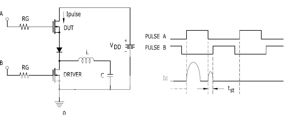
Looking at picture...First A is ON, charges L then it is OFF. Now is time that both are off, L produces negative voltage, when Id2 should be negative... Don't know for sure...it is all confusing Don't even know wich Id it is, but shoot through is only when both fets are conducting (not in this case) or body diode is too slow, so maybe this is happening..
Looking at picture...First A is ON, charges L then it is OFF. Now is time that both are off, L produces negative voltage, when Id2 should be negative... Don't know for sure...it is all confusing
Don't even know wich Id it is, but shoot through is only when both fets are conducting (not in this case) or body diode is too slow, so maybe this is happening..
It's Qrr what matters, as it's the integral of the reverse recovery current over the full recovery process (it's dependent on Id, di/dt and temperature, though). You may get an estimation of reverse recovery losses in watts with the following expression: (|Vss|+|Vdd|)*Fswitch*Qrr. You may find interesting Qrr plots in Infineon "CFD" datasheets (SPW20N60CFD and the like).
For 100V check IRF540Z. For 150V check IRFB4019pbf. For higher voltages there is not much stuff that I like in hard switched operation. Note that you don't need a TO-247 package at all, dissipation is going to be quite low in class D (particularly with music), and big MOSFET dies connected to widely spaced leads have their own sets of disadvantages.
For 100V check IRF540Z. For 150V check IRFB4019pbf. For higher voltages there is not much stuff that I like in hard switched operation. Note that you don't need a TO-247 package at all, dissipation is going to be quite low in class D (particularly with music), and big MOSFET dies connected to widely spaced leads have their own sets of disadvantages.
Download the datasheet and read. IRFB4019pbf is a 150V device so maximum rails are +/-70V or so. Next time do the math yourself 
Assuming +/-70V and 4 ohms:
70^2/(2*4)=612Wrms (at full power sine)
70V/4=17.5A peak (at full power sine)
17.5A*.707=12.37A rms (at full power sine)
17.5A*36=6.3A rms with music (with 9dB crest factor)
12.37^2*.08=12.24W max. cond. loss. (full power sine)
12.24/2=6.12W max. cond. loss. per device
6.3^2*.08=3.17W cond. loss. (music 9dB crest factor)
3.17/2=1.6W cond. loss. per device
So conduction losses are ridiculously small!! Even smaller than predicted because the body diode will clamp Rds-on during reverse conduction. Switching losses due to diode recovery and parasitistic capacitances dominate.
Now some math on IRFB4019pbf switching losses...
Lets assume an average Qrr of 160nC. That's just a quick guess (and the value shown in the datasheet). It actually varies widely depending on the input signal. There is no recovery at all during resonant operation at low signal levels, when inductor current fluctuates around 0A changing direction before each switching period ends. Then Qrr rises progressively as the system enters continuous conduction mode and body diode current becomes higher. Also, Qrr is bigger than the figures stated in the datasheet because it increases for higher di/dt and 100A/us is quite slow for hard switching. 500A/us is a more practical figure and this may make Qrr two or three times bigger.
|Vdd|-|Vss|=140V
Fswitch=250Khz
140V*250Khz*160nC=5.6W of losses due to reverse recovery alone...
Note that this is not the full story since the transistors have to pass not only the reverse recovery current but the full inductor current while sustainging the whole 140V during the full Trr of each hard switching event. Real switching losses at full power may become as high as 30W (half in each half-bridge transistor).
Well, lets make another estimation, lets assume an average Trr of 60ns and an average |inductor-current| of 6.3A.
60ns*140V*6.3A*250000Hz=13.2W additional recovery losses...
And finally, lets account for crossover losses assuming an average crossover time of 28ns (just the typical 5V/ns body diode maximum allowed slope).
28ns*140V/2*6.3A=250000Hz=3W additional crossover losses...
In other words: Go for low Qrr rather than low Rds-on.
BTW: I know that those calculations are not precise at all, but they yield quite sensible results.
hi
Ahh I allway forget that for +/-90 you need 200v fets, my mistake. Since this is half bridge, yea +/-70v is max with this fets.. as if this is not a lot... And yes low Qrr is allway better, but 4227's have quite low Qrr, compared ty fets that I have now
But if Qrr is so important then IRFB4610 would be even better or FDP3652
 Thread closed.
- Status
- Not open for further replies.
- Home
- Amplifiers
- Class D
- IR21xx + mosfet drivers