Sorry I was a bit pressed for time to reply earlier.It is, thanks!
Could you tell me some more about the measurement method? All near field?
I see the following:
- The sligthly falling total response up to 300 Hz rises again above 300 Hz
- the port output drops steeper above 300 Hz
- none of the distorsion graphs seem to follow the port output peaks above 600 Hz considering their respective multipliers
- the H2 distorsion graph is quite even and gets wiggly above 500 Hz. That follows the peak at 1k.
- H3 has a step at ~ 330Hz (thus the H2-H3 flip). Again this just reflects the response peak at 1 kHz, as far as I see. Thus I don't think it's directly related to the port.
The on axis response is at 50cm. Port response is right up it's clacker.
The rise at 1KHz is mostly related to baffle step. However the peakyness of the response is presumably a change from pistonic to modal cone behaviour. It's a 3 " driver ND91-4 so maybe that seems low in frequency but it's also got a big surround.
Here is the baffle step response.
I think you are right about the H3 going up at 300 Hz as a multiple of the 900 Hz response increase as well as probably the change from pistonic to modal behaviour.
I know you stated the enclosure is a bad example of a BP6P enclosure, but why start the experiment with a bad design?I decided to build a 6th order parallel bandpass “subwoofer” with a small 5” driver as subject for the investigations.
In addition to the port investigations I wanted to know whether a parallel BP6 has advantages compared to a simple bass reflex box.
In short, yes it does – but it’s questionable whether it’s worth it:
View attachment 1205564
- bandpass reduces distorsion output, but as far as I measured this refers almost exclusively to H2 which may not be of big concern anyway.
- the two resonators of a BP6 bandpass can reduce cone excursion (to almost zero!) at two frequencies. Between them and at lower rolloff the excursion however is bigger than bass reflex.
- the lower resonator can be tuned low and extend usable bandwidth at the lower end. of course this also increases group delay and enclosure size.
- the driver is hidden inside the box. This can be an advantage for design or protection reasons
Small low-VAS woofers such as my dayton DSA135 usually need very long (and/or very thin) ports that are prone to resonances and chuffing due to their big ratio between length and diameter; having two parallel vents adds even more resonances and provides perfect study material.
View attachment 1205565
As to be expected the simulation with hornresp proves to be very accurate and useful (thank you @David McBean !).
By changing port and chamber lengths in hornresp’s loudspeaker wizard it is easily possible to identify port and chamber resonances.
View attachment 1205571 View attachment 1205568
The hornresp bandpass wizard model does not consider losses of real helmholtz resonators, as far as i know. This explains the slightly reduced helmholtz peaks.
Mind you, this would be a bad example for a subwoofer design:
The box was built using scrap material and a cardboard tube from a fabric shop.
- using a tiny 5” driver to reach down to 40 Hz or even lower.
- long and narrow ports prone to resonances
- long enclosures with resonances near the usable bandwidth
- enclosure length similar to the port length (for chamber V1)
- ports on opposite ends reduce options for positioning the box and the resonances exiting the ports differ on both sides, creating an artificial and strange “stereo” image at close distances.
I did not use T-nuts for mounting the driver, instead i used birch plywood pieces and cut threads. This works great!
The small fullrange box for listening tests uses a sica 3,5H1CS8.
View attachment 1205570 View attachment 1205567 View attachment 1205566
Testing with a bad design fuel the BP haters. I'm a Sealed enclosure hater. They are only good for limited space in vehicles (I had 2 sealed shallow mount 15's in a 2001 F150 SuperCrew).
The test would have been more realistic if all the ports were firing in the same direction.
This might be the 1st time I've seen a BP6P with the high and low ports firing in opposite directions.
The principle of using a BP6 enclosure is to use ALL the ports together as 1 output.
You would not build a twin port BR enclosure with 1 port firing to the rear and 1 port firing to the front of the enclosure.
I cannot tell the diameter of the ports. Are they at least 1/3 of the driver's Sd?
Now I see why folks think up to 25 m/s is acceptable on avsforum.com. I TRY to stay under 16 m/s.air speeds
here are the air speeds for the narrow and wide parts of the curved wall ports, as simulated with hornresp:
C = speed of sound, 340 m/s
Input voltage Port air speed (narrow center 8,1 cm²) % of C Port air speed (wide ends 18,1 cm²) % of C 1 V 2,6 m/s 0,77 % 1,0 m/s 0,3 % 2 V 5,2 m/s 1,53 % 2,0 m/s 0,6 % 4 V 10,5 m/s 3,09 % 4,1 m/s 1,2 % 8 V 21 m/s 6,18 % 8,2 m/s 2,4 % 16 V (no chuffing measured here) 42 m/s 12,36 % 16,3 m/s 4,8 %
the straight round port (12,6 cm²) reaches an airspeed of 24 m/s (7,1 % of c) at 8 V.
from the airspeeds and measured chuffing I once more conclude that the chuffing problem is not related to the (narrow, in the case of curved walls) center section of the port but the port ends.
I should mention that while the small 5-inch driver of course has low excursion at the resonant frequencies of the bandpass chambers it will reach it's Xmax of 5 mm at frequencies between 60 and 80 Hz with around 8 V input.
so it probably makes sense to consider this a sensible limit, also for chuffing.
bad design fuel the BP haters. I'm a Sealed enclosure hater.
I did not intend to get into any haters wars! I'm not sure why anyone would get emotional about loudspeaker enclosures ... every concept has its purpose.
I also stated the reasons why I built this test enclosure, to avoid any blaming of "bad bandpass boxes". The box was very useful for my investigations!
Yes, you definitely would if you needed to isolate the port outputs for measurement.You would not build a twin port BR enclosure with 1 port firing to the rear and 1 port firing to the front of the enclosure.
Just accept that this is not a useful subwoofer but a test box to investigate port resonances and port geometries!
Once I have good results I could build a much better bandpass box - I actually will do it sometimes!
Well, this is not a bandpass but a vented box with two ports, one of which was stuffed to test the geometries.This pic backs up my BP6P post!
But I completely agree with you about positioning of bandpass ports near eachother if used as an actual subwoofer!
I did not intend to get into any haters wars! I'm not sure why anyone would get emotional about loudspeaker enclosures ... every concept has its purpose.
ALL music is emotional.
That's my point to "You would not build a twin port BR enclosure with 1 port firing to the rear and 1 port firing to the front of the enclosure."Well, this is not a bandpass but a vented box with two ports, one of which was stuffed to test the geometries.
I do understand you isolating the front and rear chamber ports in a BP6P for testing purposes though.
I would also advocate this slightly modified statement - dual or multiple ports in a single chamber potentially add unnecessary chuffing at the port ends.You would not build a twin port BR enclosure
Do you have measurements of the driver itself?Well.. for comparison here is the same driver with an L shaped port. The port response is very different, but distortion is kind of similar. So probably just a coincidence in my above plots..
View attachment 1278072
View attachment 1278073
Well they seem to match quite well actuallyActually, yes, that's a good point! I did it with STEPs instead of ARTA and the level might be a little different, but it's the same driver in a closed box of the same volume.
Yes, indeed!I wonder if there would be a difference when flaring the large vs. small sides of the rectangle slot port?
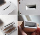
Here are the two test ports, having the same cross section surfaces, first one (left) with a flared width, second one (rigth) with flared height:
chuffing, THD and and compression results for 100 Hz and 50 Hz:
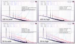
my observations:
- the width flanged port with small radius height roundover has a stronger tendency for port mode chuffing (similar to tube ports with hard edges exciting the "port whistle")
- the height flanged port is better regarding compression and correlating H3 harmonics (see 50 Hz distorsion numbers)
- the hard edges of the width flanged ports excite less low frequency noise, again similar to hard edge tube ports.
I also measured (and listened) to the flat port with a height flare, but now with a slightly increased width roundover.
this follows the same observations as stated above, the further reduced hard edges have a similar effect.
here are the two port variants (it's the same port but one with sanded and smoothed width roundover):
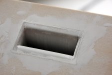
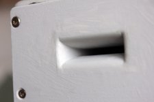
the difference is subtle, but you can see the influence by toggling the following images with the left-right arrow keys:
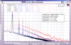
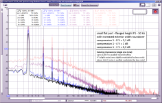
the big width roundover leads to reduced noise above 500 Hz but slightly more noise below 500 Hz.
Quite interestingly the H2 and H3 distorsion numbers differ for the 4 V and 8 V level:
I also added an audibilty comment for the big roundover variant.
bear in mind that this is a single sine tone, audibility would be reduced with more complex music masking the noise.
anyhow, I think it's best to have no noise at all!
the first consciously audible chuffing effect with percussive/modern music is usually the bass drum kicks exciting an annoying noise hiss peak.
once this gets audible the music experience is ruined and all any previous bass "authority" is gone. this usually happens long before the extended bass notes are compromised by chuffing.
I also suppose that the chuffing noises will influence the music experience even before being consciously audible.
for the very small ports shown above the bass peaks should always remain below 4 V (corresponding to 2,83 V rms). This corresponds to a SPL of only about 85 dB (2pi/1 m) so it's clear that these test ports are not useful for actual music reproduction!
the surface ratio, by the way:
driver Sd = 74 cm2
port center surface = 3,2 cm2 (only 4,3% of Sd)
port flange surface ~ 7 cm2 (9,5% of Sd - this is the relevant port exit surface that will eventually lead to turbulent air flow)
port lenght = 7,2 cm
this follows the same observations as stated above, the further reduced hard edges have a similar effect.
here are the two port variants (it's the same port but one with sanded and smoothed width roundover):


the difference is subtle, but you can see the influence by toggling the following images with the left-right arrow keys:


the big width roundover leads to reduced noise above 500 Hz but slightly more noise below 500 Hz.
Quite interestingly the H2 and H3 distorsion numbers differ for the 4 V and 8 V level:
- at 4 V the big roundover is slightly better
- at 8 V the small roundover is better
I also added an audibilty comment for the big roundover variant.
bear in mind that this is a single sine tone, audibility would be reduced with more complex music masking the noise.
anyhow, I think it's best to have no noise at all!
the first consciously audible chuffing effect with percussive/modern music is usually the bass drum kicks exciting an annoying noise hiss peak.
once this gets audible the music experience is ruined and all any previous bass "authority" is gone. this usually happens long before the extended bass notes are compromised by chuffing.
I also suppose that the chuffing noises will influence the music experience even before being consciously audible.
for the very small ports shown above the bass peaks should always remain below 4 V (corresponding to 2,83 V rms). This corresponds to a SPL of only about 85 dB (2pi/1 m) so it's clear that these test ports are not useful for actual music reproduction!
the surface ratio, by the way:
driver Sd = 74 cm2
port center surface = 3,2 cm2 (only 4,3% of Sd)
port flange surface ~ 7 cm2 (9,5% of Sd - this is the relevant port exit surface that will eventually lead to turbulent air flow)
port lenght = 7,2 cm
Last edited:
thanks for pointing this out!How does this compare to the round port of same tuning?
refer to post #469 for the round 3d-printed port and flat-width flanged port comparison with the same surfaces!
for direct comparison of round 3d-printed port and flat-height-flanged port here are the 50 Hz chuffing graphs:
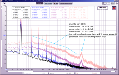
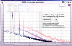
round port: more compression and much more first port mode chuffing from 4 V up! first signs of round port broadband noise at 2 V.
keep in mind that 4 V input level is already too high for these small ports. but the tendency is interesting!
scaling up the progressive port
the "progressive geometry port" proved to be quite usable in terms of resonances and chuffing, but only up to a certain input voltage level.I initially derived the geometry from an assumption of wall port curvature following progressively (and proportionally) the port cross section, or more precisely: the simplified spherical surfaces of similar air velocity in the port.
the resulting geometry resembled very closely an elliptic port wall shape.
The slow motion videos proved the assumed "spherical" movement wrong - at least for higher port particle displacement distances.
this was to be expected because of boundary layer and much more complex air movement.
the elliptic wall port shape still has advantages compared to simple straight tubes without or with flanges, as far as I experienced for low SPL:
- laminar airflow for all the port surface at low levels
- no compression, low distorsion in the laminar flow range
- small central cross section surface allows short port length (thus less lossy and higher modes)
- quite low response output resonances
- very low tendency of port mode chuffing
there is one severe disandantage, however: once the laminar flow is disrupted all negative effects of ports increase rapidly: compression, noise, distorsion.
so it is essential to keep this port in the laminar flow range.
a simple tube port will start compressing, chuffing, distorting already at low levels but these effects will increase graduallly without a sudden and violent "breakdown".
I used the small progressive port mounted to the chamber 2, tuned to 35 Hz, thus having very high air particle displacement distances.
the resulting effect and the strong correlation to the tuning/output frequency can be seen in post #448.
I then scaled the progressive port slightly up to confirm the strouhal number actually refers to the flange diameter and to see if the good properties of the geometry can be combined with a more usable dimension:
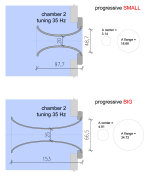
I scaled the central diameter from 2 cm to 2,5 cm, increasing the surface by 156%. the port lenght follows this ratio from 9,77 cm to 15,3 cm.
for the flange diameter I chose a compromise between geometric scaling of the ellipse and scaling the flange exit surface, leading to a surface increase of 186% (also due to installation space restrictions).
increasing the flange cross section surface by 186% and increasing the flange radius by 137% would increase the strouhal number for the same output level by 254%.
this is because the air speed and thus the particle displacement distance is inversely correlated to the cross section and the strouhal number is defined as:
strouhal number St = port radius / particle displacement
as mentioned in the roozen paper: unsteady separation of acoustic airflow for strouhal number of 1 or below.
here is the chuffing graph for the small progressive port ...
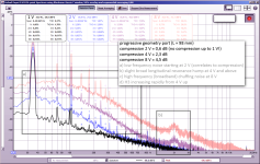
... and for the big port (including 16 V input in faint yellow):
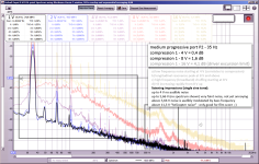
please disregard the absolute level differences. these are due to very small microphone distance from the port, still similar to the port diameter - thus no "point source").
I also included subjective noise descriptions in this graph!
here are the corresponding strouhal numbers for the flange radiusses:
small port at 2 V (start of low frequency turbulent noise) St = 0,36
small port at 4 V (turbulent noise and start of port mode chuffing) St = 0,18
big port at 4 V (start of low frequency turbulent noise, slightly less than small port at 2 V in relation to output but incuding a tiny mode chuffing peak) St = 0,42
big port at 8 V (turbulent noise and mode chuffing) St = 0,21
strouhal numbers for the central port section are all below 0,06 (faaar below 1!).
some observations:
- the port noise levels referenced above for the strouhal numbers are too high for serious music reproduction, but ok at lower input levels.
- the port lenght mode is excited slightly earlier with the big port even at slightly higer strouhal number. this is due to the worse diameter/lenght ratio.
- the increase of strouhal numbers (by ~250%) for the big port corresponds to the doubling of input voltage for similar chuffing spectra.
- the strouhal numbers for the central port area don's seem to be relevant for ports.
one more observation from another test (resuls will follow):
- very sudden increase of port diameter to achieve an acceptable strouhal number will not work, unfortunately (see image). the laminar flow cannot follow this small curvature!
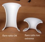
some
Last edited:
- Home
- Loudspeakers
- Multi-Way
- Investigating port resonance absorbers and port geometries