On request here’s the builders thread for the assembly of the Inverted J-FET Circlophone.
The Inverted J-FET Cirlophone PCB was initially strictly intended for personal use only, but after several private requests over time I decided to make it available for the DIY community.
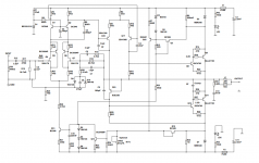
The component placement document (PDF) with reference designators matches the schematic.
The silkscreen (component) values on the inverted J-FET Circlophone PCB correspond with the schematic and are all correct, but the reference designators DO NOT match the attached schematic.
Cross-marked components without component values are ONLY for experimental use and/or a different outputstage configuration.
Highlights of this version:
Scalable outputpower, rails up to 50V
JFET input, (virtual) absence of gate/base modulation
Improved step response of the CFP configuration
Reduced phase inverter dissipation
Original Circlophone features:
No (very low…) cross-over distortion, semi class A
No need for thermal tracking the output devices
Idle current 200 mA, Gain : 28 dB
The Inverted J-FET Cirlophone PCB was initially strictly intended for personal use only, but after several private requests over time I decided to make it available for the DIY community.
The component placement document (PDF) with reference designators matches the schematic.
The silkscreen (component) values on the inverted J-FET Circlophone PCB correspond with the schematic and are all correct, but the reference designators DO NOT match the attached schematic.
Cross-marked components without component values are ONLY for experimental use and/or a different outputstage configuration.
Highlights of this version:
Scalable outputpower, rails up to 50V
JFET input, (virtual) absence of gate/base modulation
Improved step response of the CFP configuration
Reduced phase inverter dissipation
Original Circlophone features:
No (very low…) cross-over distortion, semi class A
No need for thermal tracking the output devices
Idle current 200 mA, Gain : 28 dB
Attachments
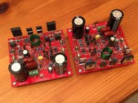
A few pics of my built...
Other earlier images can be seen here.
Other earlier images can be seen here.
An externally hosted image should be here but it was not working when we last tested it.
An externally hosted image should be here but it was not working when we last tested it.
An externally hosted image should be here but it was not working when we last tested it.
An externally hosted image should be here but it was not working when we last tested it.
An externally hosted image should be here but it was not working when we last tested it.
An externally hosted image should be here but it was not working when we last tested it.

Good job
Karl did one of the first "external" builds without much support and a lack of documentation. He did his homework and he was finished the job without a hassle. Worked flawlessly from the first power-up.")
One long legged MJL would make the build perfect. You know....
Karl did one of the first "external" builds without much support and a lack of documentation. He did his homework and he was finished the job without a hassle. Worked flawlessly from the first power-up.
One long legged MJL would make the build perfect. You know....
Thank you!Beautiful build Karl vd Berg!
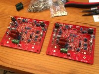
I like the idea of putting both amps on one heatsink. Are you running MOSFET output stage or BJT?
I used MJL21193 (fT 4MHz) BJT's here. Actually I'm waiting to put another pair of these without wires and on thicker heatsink.


The new PDF files are nicer, and here are 2 pictures where optional component marks are placed for experiments. My boards have resistor R38 5.6 ohm (2W) and C13 of 47nF added, though.Piersma said:...
Cross-marked components without component values are ONLY for experimental use and/or a different outputstage configuration.


Hi, xrk971Progress so far... stopped at actives and electrolytics.
Please, would you share a BOM when it's done? Curious about a few components you're using.
I am using Piersma's BOM wherever possible. Some substitutions occur for resistors that I don't have so I ether use two values in series or parallel to achieve (same or close value). I actually placed an order with DigiKey and should have just gotten everything but failed to order a few items - there is just a lot of different stuff required on this amp. I mis-ordered the 2.7k and got a 27k instead. There is a 530pF and I got 560nF by accident... on and on
I did order the Schottky diode on the rails, but had a Schottky small signal one already as the BAT14 was not in stock at Digikey.
Sure, I will try to collect a list of all my substitutions.
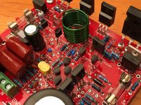
In case you are wondering about input caps - those big maroon colored things are CBB MKT 2.2uF 250V. A tight fit for sure - fat fat pins.
I did order the Schottky diode on the rails, but had a Schottky small signal one already as the BAT14 was not in stock at Digikey.
Sure, I will try to collect a list of all my substitutions.
In case you are wondering about input caps - those big maroon colored things are CBB MKT 2.2uF 250V. A tight fit for sure - fat fat pins.
(...)
In case you are wondering about input caps - those big maroon colored things are CBB MKT 2.2uF 250V. A tight fit for sure - fat fat pins.
Yes, those caps caught my attention, they are of really good quality. But I believe that the first 2.2uF input cap is *optional* for tests like other empty positions, see the C3(2) in brackets. Piersma can confirm it. I also soldered two 2.2uF input caps first, and later had the first cap removed like other resistor and another cap at left.
An externally hosted image should be here but it was not working when we last tested it.
Piersma says that an option exists for balanced input, hence two input caps - but ground the negative input for unbalanced operation as first cut to test functionality prior. There are some resistor value changes that will be coming to make the balanced version work though.
I like how colorful all the parts are on your board - nice work. Are you using a macro lens or just a close focusing cellphone cam? Photos are great - like you have a macro ring light.
I like how colorful all the parts are on your board - nice work. Are you using a macro lens or just a close focusing cellphone cam? Photos are great - like you have a macro ring light.
Ok, good then!Piersma says that an option exists for balanced input, hence two input caps - but ground the negative input for unbalanced operation as first cut to test functionality prior. There are some resistor value changes that will be coming to make the balanced version work though.
I like how colorful all the parts are on your board - nice work. Are you using a macro lens or just a close focusing cellphone cam? Photos are great - like you have a macro ring light.
I have an "old" compact Olympus XZ-1 - bought in 2011 - that has macro function. The camera has good lens.
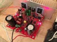
More progress, all transitors and electrolytics now in place. I did not have any 2200uF so put some pretty big 4700uF 63v ones in
I will mount to heatsink tomorrow and then test it then. Note that my Circlophone has the IRFP9240 hexFETs for the outputs.

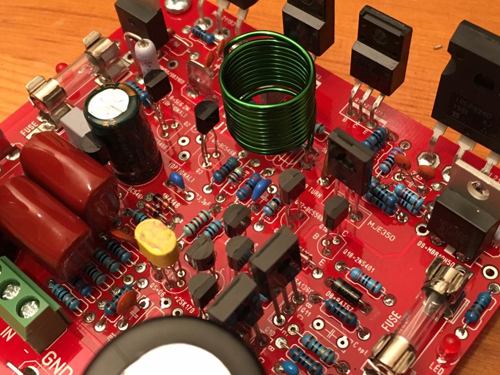
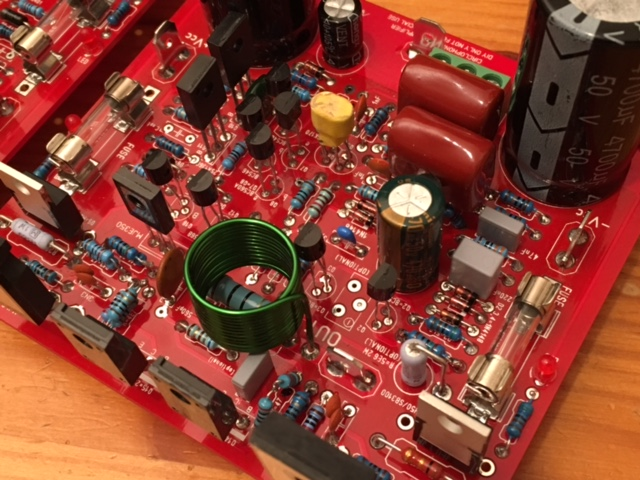
I think I counted 9 different kinds of transistors on this amp!
I will mount to heatsink tomorrow and then test it then. Note that my Circlophone has the IRFP9240 hexFETs for the outputs.
I think I counted 9 different kinds of transistors on this amp!
Attachments

Last edited:
MOSFET Circlophone #1 is ALIVE. It fired right up no issues
I am getting 180mA quiescent bias current through the 0.56R resistor. Singing now - sounds fine. Running on 35v rails at present.

Edit: the DC offset is a bit high at 80mV - although I did not bother to match the 2SK170's - would that be the culprit?
I am getting 180mA quiescent bias current through the 0.56R resistor. Singing now - sounds fine. Running on 35v rails at present.
Edit: the DC offset is a bit high at 80mV - although I did not bother to match the 2SK170's - would that be the culprit?
Attachments
Last edited:
- Status
- This old topic is closed. If you want to reopen this topic, contact a moderator using the "Report Post" button.
- Home
- Amplifiers
- Solid State
- Inverted J-FET Circlophone Builders thread