Some interesting comments by bolserst about inverted electrostats (Final, Loewe) hidden in a now closed thread about BG Neo10 magnetostatics:
https://www.diyaudio.com/community/threads/bg-neo-10-and-neo-8.204465/page-10#post-3016843
https://www.diyaudio.com/community/threads/bg-neo-10-and-neo-8.204465/post-3017520
Quote:
Most ESLs charge the diaphragm with a high resistance coating and drive the stators with audio signal from a step-up transformer.
- Advantage is vanishingly low distortion if coating resistance is high enough to achieve constant charge operation
Inverting ESLs using a highly conductive diaphragm and drive it with audio signal from the step-up transformer.
The two stators are connected to equal but opposite polarity HV supplies.
-Claimed advantage is 6dB greater sensitivity which is possible, but seldom seen in practice due to other design practicalities.
Results of comparison test between the two drive methods posted here:
http://www.diyaudio.com/forums/planars-exotics/199943-measuring-sensitivity-esls.html#post2779302
-Obvious disadvantage is the inherent non-linear driving force with conductive diaphragm,
not to mention the reliability issues with the conductive coating.
and on the question of whether inverted had inherently higher harmonic distortion
Correct.
For conventional constant charge method, force on diaphragm is proportional to signal voltage and independent of position of diaphragm in the gap.
For inverting method, force on diaphragm is proportional to the square of the signal voltage and is also a function of the diaphragm's position in the gap.
Last edited:
That intrigued me. I had a quick look at the patent attached to the first post. Geometrically, I'd say it doesn't matter whether you drive the stators or the membrane. It is never going to be fully independent of position. Let's say the distance membrane to stator is 1 mm on either side, and the membrane moves by 0.1 mm. Because of the 1/r² law, the force from the stator with the same charge decreases by 1.1² = 1.21. At the same time, the force from the stator with the opposite charge "de"creases by 0.9² = 0.81, i.e. it increases by 1/.81 = 1.235. So you get some nonlinearity, but it is compensated in first order approximation. This should be the same for both configurations.
So as bolserst points out, the culprit must be elsewhere, in the highly conductive coating. Its resistance needs to be lower in the inverting configuration for the AC signal to be roughly the same everywhere. If it had low conductivity, regions of the membrane that are far from the contact would only see a low pass filtered signal (which can be a boon if you want to have only a small area to radiate high frequencies). If you have a high conductivity, charges will move if the distance changes. I have not done the math, but I can imagine that this is where you get a voltage dependent force. If the force was purely proportional to the square, you would get second harmonic only and no fundamental. Surely, this is not the case?
So how low is low resistance? The patent shows 300 kOhms. Is that low enough to cause such nonlinearity?
This is from a review of the 1000i which uses the inverting configuration: https://hometheaterhifi.com/volume_14_3/final-sound-1000i-speakers-8-2007-part-4.html
If I read this correctly, this was 90 dB at 12 in from the membrane, so more like 80-84 dB / 1 m, depending on the radiation pattern. The second harmonic is exactly 60 dB down from the fundamental at 1 kHz (0.1% of HD2 - the 0.5% THD+N is probably owed to the LF noise in the measurement). This is lower than what good cone drivers can achieve, even if not at the > -70 dB level of the ESL 63 and its successors.
Thanks for bringing that up Charles (right?), that's interesting.
I did some distortion measurments to my ESL63's years ago and got less than 0.1% out to quite high levels.
I am intrigued by what you said here:
" If it had low conductivity, regions of the membrane that are far from the contact would only see a low pass filtered signal (which can be a boon if you want to have only a small area to radiate high frequencies) " - that seems to suggest that a non-linear conductivity might be used for electrical segmentation.
Jan
Last edited:
Let's say the distance membrane to stator is 1 mm on either side, and the membrane moves by 0.1 mm. Because of the 1/r² law, the force from the stator with the same charge decreases by 1.1² = 1.21. At the same time, the force from the stator with the opposite charge "de"creases by 0.9² = 0.81, i.e. it increases by 1/.81 = 1.235. So you get some nonlinearity, but it is compensated in first order approximation. This should be the same for both configurations.
I think this is only true with highly conductive membranes. When the membrane is so high-ohmic that the charge on it doesn't move appreciably in one cycle of the audio signal, you essentially just have a charge in a uniform electric field from the stators. You do get a very small dynamic range expansion, though, as the charge on the diaphragm increases a bit when you play at a high volume for a time that is of the order of the membrane charging time (that is, for a few seconds).
Hi Jan,Thanks for bringing that up Charles (right?), that's interesting.
I did some distortion measurments to my ESL63's years ago and got less than 0.1% out to quite high levels.
I am intrigued by what you said here:
" If it had low conductivity, regions of the membrane that are far from the contact would only see a low pass filtered signal (which can be a boon if you want to have only a small area to radiate high frequencies) " - that seems to suggest that a non-linear conductivity might be used for electrical segmentation.
Jan
you mean nonlinear as a function of lateral position? Maybe that is what they are doing. I have only begun to read up on Final.
I'm not sure I like the idea of a low pass that is implemented by the capacitance of the foil vs. the stators, something that changes with excursion, as it will give us IMD.
Hi Marcel,
how would the charge increase? That might be something we don't want as it is akin to thermal distortion in amplifieres.
Cheers
Eric
When the membrane is displaced from the centre, its capacitance to one stator increases, its capacitance to the other stator decreases and the sum of the two increases by a small amount.
When the membrane moves back and forth periodically, the sum of the capacitances to the stators changes twice per period. It changes between the value it has when the membrane is in the centre between the stators and the value it has with displaced membrane.
As a result, compared to the quiescent state, the average capacitance increases when playing loud music. As the membrane gets charged to a fixed voltage via some very large resistance, the charge on the membrane also increases when the length of the loud passage is of the order of the charging time constant or more.
It's a very small effect compared to the compression due to voice coil heating in dynamic loudspeakers, but still, it is an imperfection.

Some ESL-63 distortion measurements @ 1 meter 75 dB on axis, REW 5.30 MiniDSP UMIK-2
22 sec. sweep 10 Hz - 24 kHz, 96 kHz sample rate
1 kHz - 0.064%
500 Hz - 0.064%
400 Hz - 0.064%
300 Hz - 0.064%
200 Hz - 0.073%
150 Hz - 0.14%
100 Hz - 0.23%
80 Hz - 0.11%
70 Hz - 0.17%
60 Hz - 0.26%
50 Hz - 0.26%
40 Hz - 0.63%
22 sec. sweep 10 Hz - 24 kHz, 96 kHz sample rate
1 kHz - 0.064%
500 Hz - 0.064%
400 Hz - 0.064%
300 Hz - 0.064%
200 Hz - 0.073%
150 Hz - 0.14%
100 Hz - 0.23%
80 Hz - 0.11%
70 Hz - 0.17%
60 Hz - 0.26%
50 Hz - 0.26%
40 Hz - 0.63%
The motive force increases excessively when the membrane leaves its central position between stators (because it isn't constant charge operation). This nonlinear increasing of force is symmetrical to the central position, this causes odd-order harmonics.what is the mechanism causing odd order harmonics?
Is the push force of the opposite stator not decreasing in the same rate, making the sum of forces lineair as a result ?The motive force increases excessively when the membrane leaves its central position between stators (because it isn't constant charge operation). This nonlinear increasing of force is symmetrical to the central position, this causes odd-order harmonics.
Constant charge (Quad) Yes, but the talk was about early Final using constant voltage, in that case No.Is the push force of the opposite stator not decreasing in the same rate, making the sum of forces lineair as a result ?
@wout31
Thanks
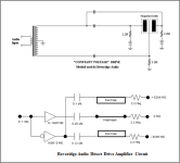
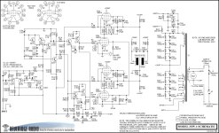
What are your thoughts about the Beveridge inverted drive method posted elsewere on this forum, where stators are also part of the drive system ?
The 2SW's are one off the best sounding electrostats i ever heard on high volumes, and use very low resistance diafram.
Of Course completely different animals, but still.
Thanks
What are your thoughts about the Beveridge inverted drive method posted elsewere on this forum, where stators are also part of the drive system ?
The 2SW's are one off the best sounding electrostats i ever heard on high volumes, and use very low resistance diafram.
Of Course completely different animals, but still.
Attachments
Sorry I can't help you there.Thanks
What are your thoughts about the Beveridge inverted drive method posted elsewere on this forum, where stators are also part of the drive system ?
The 2SW's are one off the best sounding electrostats i ever heard on high volumes, and use very low resistance diafram.
Of Course completely different animals, but still.
Never seen a Beveridge in the flesh, never heard one.
"Best sounding even at high volumes" are two subjective expressions.
Best sounding? what are distortion numbers? See my earlier post. Best sounding compared to ...... What is your reference?
High volumes? What SPL at what distance with pink noise, with music? In my opinion an ESL is not for loud, it is for precise.
If I can play 90 dB peaks at listening position with music that is loud enough for me, it is not a party speaker for a crowd.
Louder is very often more distortion. If even harmonics it's not even that annoying.
As a rule of thumb, voltage driven systems need low resistance diaphragm and constant charge need high resistance diaphragm.
Also as rule of thumb constant voltage has higher distortion numbers, constant charge has lower distortion numbers.
From what I know Beveridge is an acoustic lens design ESL, so maybe there is no comparison possible.
There are two closely related distortion mechanisms in the inverted ESL. Both are described well in Baxandall's paper.
One relates to the changing capacitance of the system with the displacement of the membrane from the central position, hence also there is a change in charge on the membrane when driven at constant bias voltage (voltage = charge/capacitance) hence change in the forces on the membrane. In the usual ESL, this problem is solved with a high-value series resistor between the HV source and the membrane preventing the change in charge on the membrane. This option is not available to the inverted ESL.
The other relates to charge migration on the membrane itself - if the membrane is not perfectly flat when displaced from the central position, charge migrates to the place on the membrane closest to a stator. In the usual ESL, the problem is solved by using the high resistivity membrane.
This distortion can be quite high, and almost entirely second order, so not especially irritating. I recall seeing a review of a Final Sound ESL exhibiting 8% distortion at high volumes (sorry, I didn't keep a copy), but I imagine it would still sound pretty good.
- Home
- Loudspeakers
- Planars & Exotics
- Inverted electrostat inferior in distortion?