spare_parts said:Check out this little circuit! Any comments would be helpful as i intend to try this one out soon. It should be about 60w into 8ohms, and runs at 50khz. Notice the lack of output inductors?!? Should one be included even though the designer did not? There is a 'pulse shaping network' that looks like a zobel or snubber there, but...
spare_parts,
looks like a fun circuit to build...
would love to build one myself...
maybe you could also post the complete article from where it originally came from..
Cheers!
DID the above(1st post) circuit... works OK!  but really needs some finishing touches..
> faster op-amp OR comparator ..
> I have "meT" -supply pumping- in action... haha bypass caps at amp was only 1000uFs...audible during low frequencies
> SHOULD use output LC filter..for wires longer than a few inches, to speaker/s
> MOSFET heat... totem-pole outputs PER mosfet gate...a must...
> add -some- deadtime
 Cheers!!
PS. arent those zener/s at GATE , a good enough addition of deadtime?? 22R in series to them perhaps??
now where is my SIM......
> faster op-amp OR comparator ..
> I have "meT" -supply pumping- in action... haha bypass caps at amp was only 1000uFs...audible during low frequencies
> SHOULD use output LC filter..for wires longer than a few inches, to speaker/s
> MOSFET heat... totem-pole outputs PER mosfet gate...a must...
> add -some- deadtime
 Cheers!!
PS. arent those zener/s at GATE , a good enough addition of deadtime?? 22R in series to them perhaps??
now where is my SIM......
RX5,
I had the same results with this circuit. If it is bridged, maybe this will solve the supply pumping. Just feeding an inverted audo signal to one half of the amp and put the load between the two should do it??? I have done this with analog amps, but don't really know if it works that simply with digital amps. Also, any suggestions for a faster opamp?
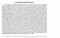
Here is as much or the original article as I can manage.
Attachments
- Status
- This old topic is closed. If you want to reopen this topic, contact a moderator using the "Report Post" button.
- Home
- Amplifiers
- Class D
- Interesting schematic
