I think that high of biasing will set this for Class B. 19v is above the typical for class B fixed bias on the data sheet for 300v B+.
Bias is actually half that value as it is cross coupled bias where bias is taken from junction of the twewo resistors (Bt and Bb)
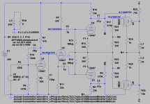
Looks like 19.4v on the cathode with 440R to ground. Is there 9v on the grids?
19.4V on the cathode and 9.7V on the grid. Notice the connection of the grid resistor to the opposing phase's voltage divider junction. (e.g. Bt)
BTW this is the version I like best so far...
Attachments
... and 9.7V on the grid.
Yep. Is the cross-coupling designed to do distortion cancellation in the OPT instead of the 6BQ5 gain stage?
The latest version looks much better as the drive current and output voltage is much higher. The 47K // 150pf loading also breaks at a much higher 55khz. Gain will be reduced about 5x you may want to add 1K grid stoppers to each grid as close to tube as possible to prevent oscillation.
The cross coupling is to reduce DC current imbalance between the two output tubes. It has bee discussed somewhat here as the Blumlein Garter circuit.
As an aside I deleted the cathode caps in the output tube cathodes as it reduced the low bass bump at the driver plates significantly which I thought would be helpful in reducing any tendancy to overload. Nothing else I tried helped. I am operating under the assumption that they are not needed for class A operation.
As an aside I deleted the cathode caps in the output tube cathodes as it reduced the low bass bump at the driver plates significantly which I thought would be helpful in reducing any tendancy to overload. Nothing else I tried helped. I am operating under the assumption that they are not needed for class A operation.
As an aside I deleted the cathode caps in the output tube cathodes as it reduced the low bass bump at the driver plates significantly which I thought would be helpful in reducing any tendancy to overload.
It would be interesting to see how much of that inverted signal is on the grid, too. It won't be pure DC, of course. Any crossfed inverted AC there is going to reduce the gain and inject some components not created in the tube it's going into, so as feedback that will get amplified instead of cancelled, until it gets wrapped back around to the prior stage from the plate FB tap.
2020,
If you are interested, the crossed AC signal to the 6BQ5 grid is minimal:
R16 33k
12AU7 rp 7.7k
Parallel of those two = 6.24k
R17 270k
6.24k/270k = 0.023
The crossed AC signal is very low: 0.023; 2.3%; or 1/43.
The capacitive reactance of the 0.47uF coupling cap is 270k Ohms at 1.25Hz.
At 12.5Hz Xc = 27k Ohms, so there is a little more crossed AC signal at the grid for Very low frequencies.
Last edited:
Oh,
Yes the 12AU7 rp is closer to 7.7k + 560 x 17 = 7.7k + 9.52k = 17,220 Ohms (but that does not include the effect of the negative feedback if it is connected/utilized). That means the crossed signals are a little larger than I stated in post #28 above.
I will let you work out the effect on the 12AU7 cathode impedance and how it affects the operating rp when the negative feedback is applied.
Things are not always as simple as at first they seem.
Last edited:
- Status
- This old topic is closed. If you want to reopen this topic, contact a moderator using the "Report Post" button.
- Home
- Amplifiers
- Tubes / Valves
- Interesting effect of Cathodyne grid resistor