Demonstrating SINE-phase shifting and B-voltage source
Behavioral Voltage Source is a handy thing, I use it to generate sine waves for my amp sims. It allows me to easily set all the details of the waveform using .param statements.
For 1KHz audio sine waves for 10 cycles, 200nS or so is a good value but for triangle waves which have sharp corners and high frequency content you need a much higher max timestep.
The second field of the .tran command is the max timestep, but you can also specify it by using
.options maxstep=10n
This article gives some reasonable rules of thumb for simulations, although it is general and not specific to LTSpice:
Spice Simulation: Setting the Transient max time step (TMAX)
The second field of the .tran command is the max timestep, but you can also specify it by using
.options maxstep=10n
This article gives some reasonable rules of thumb for simulations, although it is general and not specific to LTSpice:
Spice Simulation: Setting the Transient max time step (TMAX)
Almost ") [my oversight] in this case ".OPTIONS method=gear" saved the day together with a 10ns max-step-time
[my oversight] in this case ".OPTIONS method=gear" saved the day together with a 10ns max-step-time
And yes I do use these settings always [ehhh... most of the time .... sorry]
[my oversight] in this case ".OPTIONS method=gear" saved the day together with a 10ns max-step-timeAnd yes I do use these settings always [ehhh... most of the time .... sorry
]Attachments
Last edited:
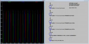
It occurred to me, you can always create a triangulair wave using a current source and a capacitor, so here one last example. Note: as the SINE-voltage source has a phase property it is easy to control the phase of generated triangulair voltage sources, the DC offset is depending on the starting phase but can be removed at the low impedance voltage source.
Attachments
Yes, to me, it's a bug.
The run-time dependency makes it even more like a bug...
Apologies to Mike (if he is reading this) it is obviously not a bug, but my mistake
It just shows, it is easy to put something together, but even for this little demo-circuits it is important to follow protocol (the one that I have includes the settings as in my latest uploads)
To any one who is/want or will-be simulating, include these settings:
.OPTIONS numDgt=7
.OPTIONS plotWinSize=0
.OPTIONS method=gear
.OPTIONS maxStep=<a number smaller than (1/frequency)/1k>
For high-simulation-fidelity the maxStep value should be less than (1/frequency)/10k or even smaller
See also post #1164 http://www.diyaudio.com/forums/soft...ice-iv-beginner-advanced-117.html#post5428105
Last edited:
I think you guys might benefit from an explanation of what the simulator does with the timestep.
The SPICE engine calculates what the circuit voltages/currents should be at one time point, and then calculates what they should be at the next time point, and so on taking into account the previous time points.
The faster things are changing in the circuit, the more time points are needed. For instance if a transistor is turning on and off for instance in a class C amplifier, more time points are needed at the switching points to collect enough data at those points that all the nonlinear behaviors can be accounted for without ruining the accuracy of the event and/or of everything that comes afterward.
Naturally the simulator tries to understand those nonlinearities as well as it can beforehand so that it can do a good job without needing to have an enormous number of points, which would take forever to calculate.
Usually there are only a few periods of the simulation that actually need that level of accuracy. So in order to save time and energy the simulator detects those points and decreases the timestep, and then increases it again when the difficult parts are over.
The simulator has different thresholds that determine when it decides it needs more resolution and how much. The problem is, what the simulator decides is needed and what the user actually needs don't always match. The default settings are meant to be usable but mainly err on the side of simulations not taking more than a minute or so to complete.
FdW's simulation shows a sort of worst-case edge case in this respect. The pulse sources are exactly understood and known by the simulator, so it doesn't anticipate any trouble. As a result, a low resolution is used and the sharp peaks of the triangle wave get lost between steps and to HF lossiness that is deliberately added to the algorithm because it is needed to keep the timestep algorithm (which is a feedback loop) stable. Okay, I'm not really sure about that, but it makes sense in my head. I'm not an expert.
The algorithm that decides what timestep to use dynamically is called the integration method, and that is what you are changing when you choose between trap, gear, or modified trap. Modified trap is default, and is mathematically superior to the others. As you have discovered, Gear gives better results in this situation, but I suspect that is because it's actually less efficient at it's job of deciding what periods need more resolution, and so errs on the side of more is better. After I learned the details of this I stopped using Gear and started specifying the timestep instead, and in my experience Modified trap is indeed better in general, and it's better to address issues with better simulation setup.
When you set maxstep=10n, you are telling the integration method algorithm that it should not use a larger timestep than this, even if it thinks things are going well. The result of this is that the simulation will never have a larger timestep than 10nS, but if say a MOSFET latches or something, the algorithm will still ramp up the resolution in order to simulate that correctly, and then revert to 10nS. I believe from experience the algorithm still keeps the steps aligned to 10nS however so that if say you specified a timestep to have a certain number of steps in the simulation, all those steps would be present at the correct regular intervals in the simulation, just peppered with bursts of smaller timesteps during fast events. So for instance your FFT will still have the same number of data points at the correct locations to work on.
So to demonstrate this, try putting a 100pF+10nESL capacitor in parallel with the second trangle generator source. In my simulation this causes everything to suddenly work fine even if no maximum timestep is specified.
The trtol parameter determines how sensitive the integrator is to rough parts of the simulation. There are often recommendations to reduce this value (which increases the tendency to ramp up the time resolution) from the default 1 to something lower. I found that reducing it to 0.1 resulted in about the same resolution and simulation time as I had manually set a power amp simulation to. I could try leaving it there but I think it's better to tell the simulator exactly what you want rather than leave it to try and make an educated guess; I don't like to be left scratching my head when it makes the wrong decision.
Last edited:
@keentoken thanks for this link Spice Simulation: Setting the Transient max time step (TMAX)
Reading the page I found a parameter 'trTol', the attached simulation shows that to get a 'perfect' triangle simulation one needs to set the value of 'trTol' to zero.
The LTspice default value for trTol is one.
See also post #1168 http://www.diyaudio.com/forums/soft...ice-iv-beginner-advanced-117.html#post5428211
Reading the page I found a parameter 'trTol', the attached simulation shows that to get a 'perfect' triangle simulation one needs to set the value of 'trTol' to zero.
...FdW's simulation shows a sort of worst-case edge case in this respect. ...
... The trtol parameter determines how sensitive the integrator is to rough parts of the simulation. There are often recommendations to reduce this value (which increases the tendency to ramp up the time resolution) from the default 7 to something lower. ...
The LTspice default value for trTol is one.
See also post #1168 http://www.diyaudio.com/forums/soft...ice-iv-beginner-advanced-117.html#post5428211
Attachments
Last edited:
Post #1163 Installing and using LTspice IV. From beginner to advanced. tries to explain that only selecting "method=gear" in combination with a smaller "stepSize" resulted in a good triangle, the other options where of minor importance (in this case) see also the posted simulation file and plot.
This one works as I described, with only the capacitor. There is still slight rounding of the points (which is also true for maxstep=10n with method=gear) but it was more to illustrate my point, I wasn't recommending to use this as a strategy.
I think trtol=0 might be too slow for some simulations. 0.1 seems to be a good value.
I think trtol=0 might be too slow for some simulations. 0.1 seems to be a good value.
Attachments
Last edited:
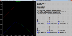
Run the simulation from post #1168 http://www.diyaudio.com/forums/soft...ice-iv-beginner-advanced-117.html#post5428211 and note that only a value for "trTol" of zero(0) will give a near perfect triangle, a value of 0.1 will not do that.
For this test use ".step param tol list 7 1 0.1 0"
The capacitor loads the voltage source and produces currents, these currents trigger the simulator to change its step behavior, this again (in this case) leads to a better result.
But, although it may/did work, I do not recommend adding components to make the simulation work it is way better control simulator (and understand it) in such a way that results are predictable. Here @DiyAudio we have a place where we can learn and teach.
Last edited:
The significance of the capacitor is that in most simulations, such components will already be present which is why your simulation is an edge case (or perhaps the triangle sources are not accounted for in the timestep calculation which should be taken up with Mike - it seems like they should be).
trtol=0 does make a slight improvement, but removing method=gear doesn't change anything for me. You have your timestep set to 24pS. I have never had a need to run a simulation this slow. What is your criteria for an accurate simulation?
Like I already said, I don't recommend the capacitor thing as a strategy. It was just to demonstrate what is going on.
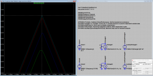
The setting ".OPTIONS method=gear" was the largest contributor to precision of the simulation when "trTol" was not (yet) considered.
Using only "trTol=0" gives a near perfect triangle [that is not a slight improvement but a large one] (no other settings needed, see attached picture where "trTol" is stepped 7, 1, 0.1 and 0).
The point is, everyone can select his own value(s) (as desired or needed) we can only advice, e.g. I'm not saying one should use a value of zero, I'm only saying that the default is 1 and the usable range (for as far as I can see/find in documentation) is 7...0 (for ".OPTIONS trTol = <...>")
Please note that (as shown in the attached screen-shot) that all other options than "trTol" where disabled when the attached graph was generated.
Using only "trTol=0" gives a near perfect triangle [that is not a slight improvement but a large one
] (no other settings needed, see attached picture where "trTol" is stepped 7, 1, 0.1 and 0).The point is, everyone can select his own value(s) (as desired or needed) we can only advice, e.g. I'm not saying one should use a value of zero, I'm only saying that the default is 1 and the usable range (for as far as I can see/find in documentation) is 7...0 (for ".OPTIONS trTol = <...>")
Please note that (as shown in the attached screen-shot) that all other options than "trTol" where disabled when the attached graph was generated.
Attachments
Last edited:
I just wanted to tell people how these parameters work so they have an idea what to mess with and what not, and why.
I think the best policy is to always specify your max timestep, especially if you want to do an FFT of the results or export to a .wav file.
Maybe a more informative test would be to run .wav files through a simulation with different integrator settings and compare integrator distortions in the output.
Triangle needs very high bandwidth, and as such also fast steps in ltspice?. Oke guys, thanks for the work, now we all have learn again about spice, this sogtware has a lot hidden possibillities, maybe include it into the voltage source will help a lot, with that I mean the delay function so we do not have to type a half book before it works right.
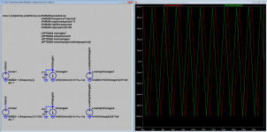
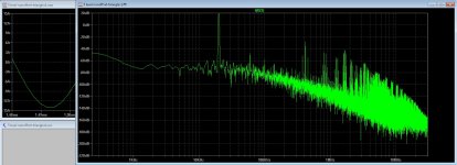
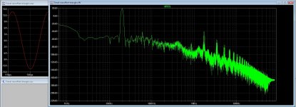
I have try it now and it is oke, now I have the good signals but there is some difference,when using normal integrator opamp with flip flop I get better signal als with the solution I seen here, the suppression of the carrier with the 5 level class d is much less then the normal opamps version, see pic one, pic two is with the normal opamps and carrier looks much better, this happes when fase is not pefect between the triangles...
regards
To a wav file? is that possible, I did not now.
Attachments
- Home
- Design & Build
- Software Tools
- Installing and using LTspice IV (now including LTXVII), From beginner to advanced