We cannot be sure what parameters Peter Walker specified for selection for the RCA house numbers, possibly reducing design variation, but I do feel that some of the LTSpice models need some correction. Aside from some RF transistors and very specialised parts like TV line output transistors, most transistors have very similar Vbe behaviour at moderate currents
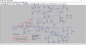
The readings from my sim. now agree with Mooly's - 0.59V input gives 17.11Vrms (36.5W average) out. At 0.65V in, it's 18.5V (44.4W) out, but just into clipping. I agree, the interaction between Vmidpoint and bias is terrible on that original bias circuit. The later version is a lot easier to adjust, though still a bit tricky.
On another point - I believe that the rule-of-thumb is (Bob Cordell and others) that good biasing will put 52mV across the two o/p emitter resistors. This sim gives just 9.5mV (2x4.45). Are triples different? (though Cordell mentions this figure in a para where he also mention triples, which suggests that they too comply with this).
David - I also wondered if some of the things I was seeing are artefacts of Spice, which is why I started this discussion on the thread. Presumably Quad did "real world" measurements when they published specs of the 303 (no simulators in the 1960s!)
Distortion on many commercial amplifiers used to be adjusted (although not sure if Quad would do this though) using a distortion analyser.
These days we do apparently have rules of thumb that relate the output stage configuration to a recommended bias level although one problem with 'triples' is that there are quite a few different variations of configuring them.
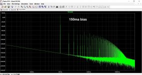
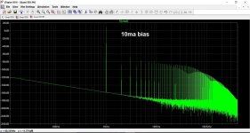
You have to assume the Quad recommended 10ma is based on measured performance for lowest distortion although other factors often play a part in commercial gear such as heatsinking and how thermally stable the design is. Ideally a bias setting should remain constant from a cold start to say 60C case temperature. In practice very few designs approach anything like that.
These days we do apparently have rules of thumb that relate the output stage configuration to a recommended bias level although one problem with 'triples' is that there are quite a few different variations of configuring them.
You have to assume the Quad recommended 10ma is based on measured performance for lowest distortion although other factors often play a part in commercial gear such as heatsinking and how thermally stable the design is. Ideally a bias setting should remain constant from a cold start to say 60C case temperature. In practice very few designs approach anything like that.
Does anyone know if it is possible in LTspice to make waveforms 'stick' between runs?
For instance, I do a run, display a waveform, then change something, do another run and display the new waveform overlaying the previous one?
It's a very useful trick I do with audio equipment like AP or dScope but not sure it is possible with LTspice.
Jan
For instance, I do a run, display a waveform, then change something, do another run and display the new waveform overlaying the previous one?
It's a very useful trick I do with audio equipment like AP or dScope but not sure it is possible with LTspice.
Jan

Yes I use the .step as well. But this is a circuit where I made a substantial change in the circuitry itself, and was looking for an easy way to plot the two waveforms in the same pane.
It seems you can open a previously saved waveform but that then gets its own new pane and while you can copy waveforms between panes, this can only be done within the same run it seems.
Jan
It seems you can open a previously saved waveform but that then gets its own new pane and while you can copy waveforms between panes, this can only be done within the same run it seems.
Jan
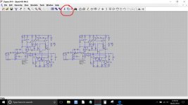
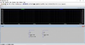
One other way is to scroll the circuit you have and make it small, then use the copy function to draw around and then drag the copy alongside.
Now delete any duplicate .op commands etc and alter as necessary any duplications in shared rails/outputs and so on.
You can then run the two circuits together and alter one while keeping the other the same.
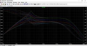
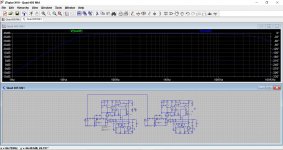
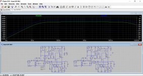
(one odd thing with this example that I can't fathom. If I keep the two input voltages separate then the second circuit has a gain 6db higher than the first on an 'AC Analysis' run, however a 'Transient' run shows the same output voltage. Why is that ?)
Now delete any duplicate .op commands etc and alter as necessary any duplications in shared rails/outputs and so on.
You can then run the two circuits together and alter one while keeping the other the same.
(one odd thing with this example that I can't fathom. If I keep the two input voltages separate then the second circuit has a gain 6db higher than the first on an 'AC Analysis' run, however a 'Transient' run shows the same output voltage. Why is that ?)
Attachments
First picture was wrong one above. Should be this:
I have been playing with that but you must make sure that the sources and node names have different names (they will not when copied) or feed both circuits from the same source.
Jan
Thanks Jan... I'm puzzled as I'm sure I got that right.
I didn't save the sim, but I do have another 'dual' sim set up for Doug Selfs old precision preamp and I see exactly the same issue there. In fact the 6db difference is present on the input voltage source itself.
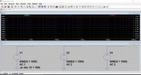
Nutz... lets try a voltage source on its own repeated three times. Hmm, so this also gives a 6db 'increase' for the first copy and another increase of around 3.5db for the third copy.
I must be overlooking something really obvious but I can't fathom it.
I didn't save the sim, but I do have another 'dual' sim set up for Doug Selfs old precision preamp and I see exactly the same issue there. In fact the 6db difference is present on the input voltage source itself.
Nutz... lets try a voltage source on its own repeated three times. Hmm, so this also gives a 6db 'increase' for the first copy and another increase of around 3.5db for the third copy.
I must be overlooking something really obvious but I can't fathom it.
Attachments
What's your problem.Thanks Jan... I'm puzzled as I'm sure I got that right.
I didn't save the sim, but I do have another 'dual' sim set up for Doug Selfs old precision preamp and I see exactly the same issue there. In fact the 6db difference is present on the input voltage source itself.
Nutz... lets try a voltage source on its own repeated three times. Hmm, so this also gives a 6db 'increase' for the first copy and another increase of around 3.5db for the third copy.
I must be overlooking something really obvious but I can't fathom it.
V1 is 1 Volt, V2 is 2 Volt and V3 is 3 Volt, resp 0dB, 6dB and 9.54dB.
Everything is O.K.
Also in your dual Amp diagram one source is 1 Volt and the other 2 Volts, so output is 6dB higher for the second Amp.
Hans
Thanks Hans, a true mental block on my part ")
I was thinking when I duplicated the circuit I would have to change the 'voltage reference' designators manually to avoid duplication and for some reason I kept going to the 'AC Amplitude' box on the voltage sources thinking it was that.
Duh
I was thinking when I duplicated the circuit I would have to change the 'voltage reference' designators manually to avoid duplication and for some reason I kept going to the 'AC Amplitude' box on the voltage sources thinking it was that.
Duh
 Thanks for the update.
- Home
- Design & Build
- Software Tools
- Installing and using LTspice IV (now including LTXVII), From beginner to advanced