
I have found a simulation model of a sic mosfet who is interesting, but ltspice do not sim with it well, no graph and it error later on.
Did try everything with no succes, it just show no graph, with the others it do fine so model of that mosfet is not oke maybe some ltspice professors here can look at it.
thanks.
Did try everything with no succes, it just show no graph, with the others it do fine so model of that mosfet is not oke maybe some ltspice professors here can look at it.
thanks.
Attachments
Example:
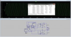
.model C2M0025120D_AB VDMOS(Rg=1.1 Vto=2.25 Rd=-5m Rs=20m Rb=6.7m Kp=2.6 Ksubthres=.1 Mtriode=3 Theta=20m Lambda=40m Cgdmin=15p Cgdmax=2n Cgs=2825p tt=15n ibv=1.5m nbv=20 a=0.7 is=3.6p cjo=2.52n bv=1600 m=0.368 EG=3.26 vj=0.6 n=3.9 Vds=1200 Ron=25m
I have tryed these one.
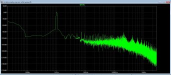
results from a allfet circlotron see pictures, not bad.
Attachments
Hi, I was trying to determinate the output impedance of a circuit, following the instructions here: 15/ Measuring amplifier output impedance. Post #214
the circuit is this, (attachment), from an idea of fellow member Ketje
sure I'm missing some crucial detail, because I'nt getting nothing resembling an impedance plot
I'm trying to know if this circuit is usable with a certain "difficult" SS amplifier input stage
Hope someone can point me the right direction
Cheers
J.
Attachments
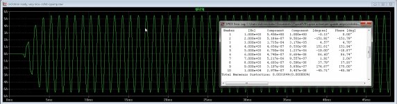
I've taken your schematic and done the following:
1. added I1 across the output, set to AC=1
2. zeroed out the AC component of the input source
If you run an AC simulation, and look at Vout (on a non-dB basis), the resultant voltage numbers correspond to the output impedance.
I can double check it if you can include your tube models.
1. added I1 across the output, set to AC=1
2. zeroed out the AC component of the input source
If you run an AC simulation, and look at Vout (on a non-dB basis), the resultant voltage numbers correspond to the output impedance.
I can double check it if you can include your tube models.
Attachments
I can double check it if you can include your tube models.
Sure I can, and many many thanks
(change .txt to .inc if necessary)
Attachments
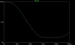
It looks like it can hit the desired target: "The input resistance is ~10K, but the source impedance is preferably kept below 1K, because of the base current modulation caused by the bias servo."
Anyway, the instructions posted where right, I forgot to zeroing the signal source. Great instructable.
Thank You very much
J.
Anyway, the instructions posted where right, I forgot to zeroing the signal source. Great instructable.
Thank You very much
J.
Last edited:
- Home
- Design & Build
- Software Tools
- Installing and using LTspice IV (now including LTXVII), From beginner to advanced