This is the point I right clicked the executable file and tried Windows own compatibility trouble-shooter. Setting the Windows version to anything but W10 appeared to instantly fix the issue.
That's a good one, I always forget about that tool (and it can be a lifesaver
") )
)Conclusions... I am forced to believe on the evidence that some Windows processhas been altered or updated silently causing the issue. The two PC's affected are pretty much identical in configuration and 3rd party software but years apart in hardware terms.
Yes, I do agree (at the least you have one person agreeing
)And besides this... there is still (in lots of cases, the video drivers may be propriety and getting old [if your system has been updated to here over the years]) the possibility that renewing drivers (as above explained) will improve future (and current) issues (one of them being compatibility).
Video drivers are a pain. Both PC's in question are laptops, one modern(ish) Dell i5 and the other an ancient Acer with an AMD64 Turion CPU with NVidia GeForce graphics.
Finding a driver (actually drivers for several things) for the Acer to run W10 was a struggle, the Dell was a breeze with pretty much everything getting picked up automatically.
Oh well, until the next disaster strikes
Finding a driver (actually drivers for several things) for the Acer to run W10 was a struggle, the Dell was a breeze with pretty much everything getting picked up automatically.
Oh well, until the next disaster strikes
I have used logic in ltspice, I sim'd up a St1000A fm signal generator, the parts in the library are basic, in that they toggle from 0 to 1V. There is no propagation delay, perfect slew, I have no idea how to model specific technologies like CD4xxxx or 74xx. I guess you would have to make models for them out of primitives. Lots of work.
Hi!Re-establish the connection and LT is broken again. LT IV is not affected on either system.
What do I do if I don't want to show the Big Brother of my research? I'll have to abandon the new version of the program.
Hi!I am the same, I did find a few small mistakes in the tutorial. maybe it was my initial confusion.
You can select multiple points to view THD and see the contribution of each cascade to the overall distortion of the amplifier. Without breaking the NFB loop, it is possible to estimate the distortion of the amplifier and its cascades to the coverage of the NFB.
Attachments
Hi!
What do I do if I don't want to show the Big Brother of my research? I'll have to abandon the new version of the program.
Did you read post #720 about running in compatibility mode ? I haven't had any issues since doing that.
From what I've modeled, the most interesting - opamp uA702. Very few of opamps that have Ku for about from 2000 to 10000 times in the band over one megahertz. Of course, it has a low maximum output voltage, but it is only linear opamp. Especially when you consider the times, when it was design. It has low distortion, 0.000,13% for the 20K frequency and output voltage of 500 mV.
http://s1.stuffed.ru/y2016/12-31/0/465554.png
If little to improve circuit frequency compensation and circuitry (Q10Q11), its distortion can be greatly reduced, look at the model uA702.1.
http://s1.stuffed.ru/y2016/12-31/0/465574.png
The circuitry of this opamp can be a good basis for a transistor preamps.
An externally hosted image should be here but it was not working when we last tested it.
http://s1.stuffed.ru/y2016/12-31/0/465554.png
If little to improve circuit frequency compensation and circuitry (Q10Q11), its distortion can be greatly reduced, look at the model uA702.1.
An externally hosted image should be here but it was not working when we last tested it.
http://s1.stuffed.ru/y2016/12-31/0/465574.png
An externally hosted image should be here but it was not working when we last tested it.
The circuitry of this opamp can be a good basis for a transistor preamps.
Attachments
Last edited:
Additionally, Vaf also needs to be specified, since Early effect shunts every collector with a nonlinear impedance and is often a dominant distortion.
R4 is vestigial. If you remove it and make R1,R3=30k, loop gain will be increased by as much as 3 times in the audio range.
R4 is vestigial. If you remove it and make R1,R3=30k, loop gain will be increased by as much as 3 times in the audio range.
I agree. I just played within the circuitry, of anything serious. In the place of R1,R3, it is necessary to put CS, and to increase the input impedance of the next stage to apply of followers.Additionally, Vaf also needs to be specified, since Early effect shunts every collector with a nonlinear impedance and is often a dominant distortion.
R4 is vestigial. If you remove it and make R1,R3=30k, loop gain will be increased by as much as 3 times in the audio range.
It was a long-long time ago. This opamp installed in my automatic meter nonlinear distortions in cascade the automatic gain control. I needed opamp high gain to at least 200 kHz to evaluate 10 harmonics of the signal frequency 20K. I could not replace it with any of the new opamp, order not to worsen the distortion introduced by the cascade. I had to replace it russian equivalent CA3015. This improved opamp approximately with the same circuitry.
Last edited:
LTSpice does need an Internet connection to check for updates. Otherwise it shouldn't be going online at allJudging by the photos, it seemed to me that the program does not want to work without Internet connection. For me it's suspicious.
Positive grid region
Hello all.
Is there any easy way to add the positive grid region in tubes models, to be used, for example, in class C oscillators, class AB2 amplifiers, multivibrators and blocking oscillators? Adding an external diode doesn't help because this way we lose the high current spike in the anode circuits.
Any help welcome.
Thanks in advance.
Problems trying to use .wav files or PWL files.
This is something I have never tried before and tbh the problems I seem to be having made me wonder if anyone has any practical experience of all this.
I've followed the LT tutorial on using wave files as a signal source and found I had mixed results in that it either worked straight off or 'froze' with an 'initializing matrix' message.
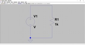
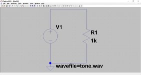
So the circuit is as simple as possible consisting of a voltage source and a 1k load.
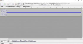
The .wav file is a 60 second mono track of a sine wave created in Audacity, the audio exported as a .wav Microsoft Signed 16 bit 44.1kHz file. Standard stuff.
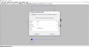
I hold down 'CTRL' and right click the voltage source adding the .wav file.
When I run the sim it all works. Yea
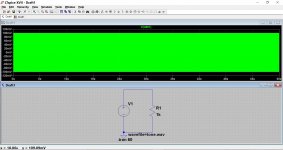
The problem is that if I add any complications to the .wav file (such as a fade in or a few seconds silence) then the sim appears not to run, I just get the initializing matrix message. The LT example shows a complex music waveform being added with no issues so I'm a little lost at this point why the slightly altered wav file wont run.
The Audacity screenshot just shows confirmation of the single tone. It when I alter this that LT will not run, for example by adding a fade in at the start or silence part way through.
This is something I have never tried before and tbh the problems I seem to be having made me wonder if anyone has any practical experience of all this.
I've followed the LT tutorial on using wave files as a signal source and found I had mixed results in that it either worked straight off or 'froze' with an 'initializing matrix' message.
So the circuit is as simple as possible consisting of a voltage source and a 1k load.
The .wav file is a 60 second mono track of a sine wave created in Audacity, the audio exported as a .wav Microsoft Signed 16 bit 44.1kHz file. Standard stuff.
I hold down 'CTRL' and right click the voltage source adding the .wav file.
When I run the sim it all works. Yea
The problem is that if I add any complications to the .wav file (such as a fade in or a few seconds silence) then the sim appears not to run, I just get the initializing matrix message. The LT example shows a complex music waveform being added with no issues so I'm a little lost at this point why the slightly altered wav file wont run.
The Audacity screenshot just shows confirmation of the single tone. It when I alter this that LT will not run, for example by adding a fade in at the start or silence part way through.
Attachments
- Home
- Design & Build
- Software Tools
- Installing and using LTspice IV (now including LTXVII), From beginner to advanced