There are two same output named "out".I dont know how repair this mistake.
Rename one to "out1".
Last edited:
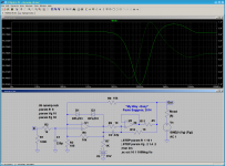
Now I am represent on your judgement my method construction graph of output resistance. For its calculation I used euation Rout=Rload1*Rload2*(Uout2-Uout1)/(Uout1*Rload2-Uout2*Rload1)
I run simulation with 4Ohm Load and 8Ohm Load and plot the graph.
Obserw result please. Criticism is welcomed.

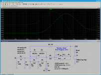
I run simulation with 4Ohm Load and 8Ohm Load and plot the graph.
Obserw result please. Criticism is welcomed.
For those who may be unaware, there is a huge collection of circuits, easily accessible, to play around with here, Components Library and Circuits - LTwiki-Wiki for LTspice - which includes greatly enlarged libraries of device models: The whole library replacement with additions plus tons of examples as one zip file - about 33 MEG.
Last edited:
There is no need to use the equation, LTSpice is able to plot the output impedance directly (assuming the amp simulation works and all the SPICE models used are fairly accurate). You can do this by shorting the input of the amp to ground, connect a 1A current source to the output of the secondary and ground, then plot the output voltage, please try it and see if this works for you.For its calculation I used euation Rout=Rload1*Rload2*(Uout2-Uout1)/(Uout1*Rload2-Uout2*Rload1)
Fair enough - it's good that you add this warning here about such. However, I feel it's worthwhile making people aware of what resources are about, that are easy to access - the circuits therein are something to be explored, to give people ideas about what can be done.
In terms of culling, what would you recommend as a guide for the good, vs. the bad?
In terms of culling, what would you recommend as a guide for the good, vs. the bad?
It not wrong to share, I just want to point out that there is no free lunch. You should check that your models work.
There are a lot of BJT models that have Cje=2p. These are all bad (except maybe for a few that really do have Cje=2p). That will eliminate a lot of bad models of japanese transistors. Models from Phillips/NXP are usually good.
There are a lot of BJT models that have Cje=2p. These are all bad (except maybe for a few that really do have Cje=2p). That will eliminate a lot of bad models of japanese transistors. Models from Phillips/NXP are usually good.
much better than that, you can connect a sine voltage source in series with a resistor equal to the typical amp load (e.g. 8 ohm) at the amplifier output and plot the amplitude/phase diagram WRT frequency (AC response).There is no need to use the equation, LTSpice is able to plot the output impedance directly (assuming the amp simulation works and all the SPICE models used are fairly accurate). You can do this by shorting the input of the amp to ground, connect a 1A current source to the output of the secondary and ground, then plot the output voltage, please try it and see if this works for you.
This will tell you not only the output "impedance" (resistance) at DC (which can be easily calculated from the attenuation shown on the plot), but will actually show you how it will behave (modulo and phase) with varying frequency.
That's a much more useful information.
")
(P.S.: do not believe that the typical behavior of a conventional, real-world amp is to have a nicely low, almost constant and purely resistive output impedance as shown in one of the attached plots: quite the contrary! Try and see for yourself...)
Attachments
Last edited:
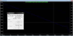
Not sure where to ask this question so I try here. I'm simulating the open loop gain of a circuit. The phase margin (87 deg) and gain margin (24 dB) looks OK, but there is a slight gain peak at around 28MHz, and I would like to know if it's a sign of oscillation.
Attachments
Last edited:
Just posted this in the Symasym Thread
Has this been explained in this Thread, including models in the asc. file rather than having them in a look up folder?
Have just finalised the stability components on a 1943/5200 version of the Symasym.
Will do the second channel and then report my findings.
I will probably include an asc file to show where my version is very slightly different from the Pavel modified version.
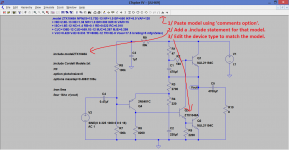
How do I include Cordell models in the asc so that everyone that wants to play can use the same models as everyone else?
Has this been explained in this Thread, including models in the asc. file rather than having them in a look up folder?
Just posted this in the Symasym Thread
Has this been explained in this Thread, including models in the asc. file rather than having them in a look up folder?
I didn't cover this as an option because I felt it was visually messy (if more than say one model is needed).
The diagram shows the steps. You need to acquire the model wanted and make sure it is in a form usable by LT and then paste the model onto the diagram as shown.
Attachments
Pinched from another forum ...Did anyone find a way to fix the Y-axis scales within a project?
Especially with X-over filters one is more interested in the -3db than in the -120db..... Now I constantly have to retype the proper settings
Here's the answer, from the horse's mouth (Hemut at the LTSpice forum):
The solution is using plot settings.
Run the simulation. Set the scale.
Plot Settings -> Save Plot settings
Next simulation run.
Plot Settings -> Reload Plot settings
Next simulation run.
Plot Settings -> Reload Plot settings
...
You can set a hot key for "Reload Plot Settings".
It seems several user have set the spacebar as hot key.
I wholeheartedly agree, but it is the most straight-forward way to guarantee that specific models will be used in your simulation.I didn't cover this as an option because I felt it was visually messy (if more than say one model is needed) . . . . .
From time to time I suggest to the LTSpice Yahoo Group that there should be a "Models" tab in the basic LTSpice screen, where you could collect the models pertaining to a particular simulation. Or, a feature to export ALL of the models from a simulation into a single file - perhaps with the same filename as the *.asc circuit file, but "*.mdl" or "*.lib" for the extension. Then, set an option to make this the second option when LTSpice goes searching for device models. (The *.asc file itself would remain as the first option in the search path.)
So far, I haven't received any support for these ideas.
Dale
Pinched from another forum ...
Thanks Frank, I wouldn't have had a clue on that.
I wholeheartedly agree, but it is the most straight-forward way to guarantee that specific models will be used in your simulation.
That sounds a totally reasonable suggestion to me although I guess it would need some major rewriting of the basic program files.
I have downloaded a few .asc to run as a learning exercise.I wholeheartedly agree, but it is the most straight-forward way to guarantee that specific models will be used in your simulation.
From time to time I suggest to the LTSpice Yahoo Group that there should be a "Models" tab in the basic LTSpice screen, where you could collect the models pertaining to a particular simulation. Or, a feature to export ALL of the models from a simulation into a single file - perhaps with the same filename as the *.asc circuit file, but "*.mdl" or "*.lib" for the extension. Then, set an option to make this the second option when LTSpice goes searching for device models. (The *.asc file itself would remain as the first option in the search path.)
So far, I haven't received any support for these ideas.
Dale
But they don't run. They have used models that are not in the LTspice library. Frustrating !
- Home
- Design & Build
- Software Tools
- Installing and using LTspice IV (now including LTXVII), From beginner to advanced