The resistance used varied somewhat with the specific amp and the time that the amp could possibly be in the "slow start" state.
With a manual switch that could (and has been) all day, unless you pay attention. So that was a 100watt resistor, iirc.
With the timed circuits, I used a long charge time, in the multiples of seconds, like 10-20 seconds (again iirc), so the resistors were smaller, I think those were probably 35 or 50 watt units. At the time I picked pile of them up surplus and inexpensively, and (again iirc) put two or three in series to get the requisite resistance, although that might have been in parallel for more power - again the final resistance was the key.
I determined the actual resistance empirically, watching the charge % and time it took to get there vs. the final current surge.
Keep in mind that one version of the amp used >4kva xfmrs and the "smaller" supply was >2kva so there is some inductive "pop" to contend with as well.
I'd not try to do an amp with this much capacitance today. Back then large "computer grade" electrolytics were reasonably priced and available. I did that much capacity with only 6 cans!
Today, I'd likely opt for getting some "fast" capacitance very near to the output devices as one method that I have heard is effective.
Ymmv.
_-_-
Startup time of 10-20 seconds is pretty high and can I know how are you calculating the resistance values required? can you please take a case study of
3.3KVA trafo with 2,00,000uf per rail so total for two rails its .4F so how do you calculate the resistance in the above case in terms of Resistance value and Power of the resistor. It will help alot in decide...
If you like to know for sure, model the PSU via say Duncan Amp and it will give you the turn on spike. From there you can just use Ohms law to figure out what wattage of resistor to use to figure out what wattage resistor to use.
However, I don't think you mentioned what circuit / amp etc you have behind this massive power supply you are building.
This is important. If you have say a Class A circuit then you MUST take into account the current draw that circuit will demand on startup. Class A/B will have less demand, but you need to know what the constant draw is at idle. That MUST be factored into your soft start/ slow charge design.
As I said earlier, in my case I have a 1.5kVa trafo with 0.564F cap bank at 52Vdc with a class A circuit drawing 6A at 52Vdc behind all that. A soft start with a 10A fuse will NOT work in my case. I had to design a separate slow charge circuit after the trafo in order to slowly charge up the cap bank. In my case I used NTC's in series with a relay to switch them out after about 18secs of charging.
Why do you keep getting this wrong.3.3KVA trafo with 2,00,000uf per rail so total for two rails its .4F
It is confusing.
K = Kelvin (temperature)
k = kilo (10^3 multiplier)
f = fempto
F = Farad
Why add extra "," ?
do you mean 200mF, or 2F?
In addition, omitting the leading zero in a decimal number < 1, can be misread.
type it as 0.4F
post64 link had a following post
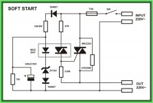
The timing varies enormously with Mains supply voltage. It can reach the point that on low supply voltage, the relay does not bypass and the resistor, then require to be rated for MANY kilo-Watts.
and TNT replies withThat's safer.
But still no fuse.
Add a real timer to trigger the relay, not a voltage dependant RC
The example shown is a very bad timer circuit.But then it's not *very* simple anymore
The timing varies enormously with Mains supply voltage. It can reach the point that on low supply voltage, the relay does not bypass and the resistor, then require to be rated for MANY kilo-Watts.
This is the correct analysis...................As I said earlier, in my case I have a 1.5kVa trafo with 0.564F cap bank at 52Vdc with a class A circuit drawing 6A at 52Vdc behind all that. A soft start with a 10A fuse will NOT work in my case. I had to design a separate slow charge circuit after the trafo in order to slowly charge up the cap bank. In my case I used NTC's in series with a relay to switch them out after about 18secs of charging .
A soft start to "START" the transformer. Any following capacitance/inductance does NOT affect the soft start circuit, nor the components selected to enable the ~200ms delay.
The capacitance AFTER the transformer is what may require a slow charge.
The CURRENT through the rectifier is controlled/limited by the slow charge resistance.
Except:
should say:In my case I used NTC's in series with a relay to switch them out after about 18secs of charging
NTC's in parallel with a relay to switch them out
Last edited:
"Build An Energy Storage Bank" article
Yes, Tony did ask me about posting that article, which covers a lot of things discussed here. I thank him for the courtesy of requesting permission to post the article, which was: "Build An Energy Storage Bank, Walter G. Jung, Audio, August 1980". While it would certainly fit into the context of this DIYAudio thread, I really can't recommend it any longer, and so I have declined the request to make it unconditionally available. As noted within, it isn't a beginner project.
Among the reasons for this is the fact that there are subtle downsides to using such a filter bank, which many might not fully appreciate. The (very) high current pulses in the caps generate RFI, which can be a problem, even when the system is carefully constructed and all of the appropriate soft-start issues are fully addressed. As a DIY add on project, this point is particularly cogent, since the caps must be outside-the-box. Also, the added wiring, connectors, etc. will tend to negate part of the effectiveness of the ultra-low Z of the bank as seen right at the terminals. By contrast, look at the Bear Labs internally mounted, buss-bar strapped filter caps: http://bearlabsusa.com/NEXT/SYMPHPS.jpg
Having said all this, I don't wish to be seen as preventing information to be shared. If anyone is in dire need of my Audio article, simply email me, via DIYAudio or my website contact page.
Walter Jung wrote a detailed construction article
in the Audio Magazine sometime in 1980,
i have scans of that article but i can not post it here due to IP issues....
*
he used a 10 ohm/ 50 watt Dale power resistor, a 555 timer and a relay...
soft starting circuit need not be overly complicated....
*
as generous as i am with psu filtering,
i am likewise generous with switches and relays....
i will use a relay rated for 15 amps contact,
you can use the same for 240 volt mains,
a dpst mains switch rated for 15 amps is what i will use...
Yes, Tony did ask me about posting that article, which covers a lot of things discussed here. I thank him for the courtesy of requesting permission to post the article, which was: "Build An Energy Storage Bank, Walter G. Jung, Audio, August 1980". While it would certainly fit into the context of this DIYAudio thread, I really can't recommend it any longer, and so I have declined the request to make it unconditionally available. As noted within, it isn't a beginner project.
Among the reasons for this is the fact that there are subtle downsides to using such a filter bank, which many might not fully appreciate. The (very) high current pulses in the caps generate RFI, which can be a problem, even when the system is carefully constructed and all of the appropriate soft-start issues are fully addressed. As a DIY add on project, this point is particularly cogent, since the caps must be outside-the-box. Also, the added wiring, connectors, etc. will tend to negate part of the effectiveness of the ultra-low Z of the bank as seen right at the terminals. By contrast, look at the Bear Labs internally mounted, buss-bar strapped filter caps: http://bearlabsusa.com/NEXT/SYMPHPS.jpg
Having said all this, I don't wish to be seen as preventing information to be shared. If anyone is in dire need of my Audio article, simply email me, via DIYAudio or my website contact page.
Last edited:
FWIW, NTC resistors are made to run hot, look at the millions
of ATX power supplies out there, some even run 24/7....
i use NTC's on both the primary/secondary sides of my tube amps,
i use them in the filament supply if i wanted to lose a few mV.....
a resistor shorted by a relay contact is the best option for me...
it need not be too high a value so as not to break the fuse in the event of a malfunction...
Yes.
NTCs are good.
Resistors can be made to be good.
For low source impedance, any added resistance, whether by NTC, or resistor, should be bypassed for good overall performance of the following circuit. Except for the VERY few circuits that perform better with a high source impedance.
NTCs are good.
Resistors can be made to be good.
For low source impedance, any added resistance, whether by NTC, or resistor, should be bypassed for good overall performance of the following circuit. Except for the VERY few circuits that perform better with a high source impedance.
Hey! WaltJ!
Thanks for the kind mention!
Made my day.
Fwiw, even with that rather heavy buss bar approach, there is still really significant current and vdrop *inside* or *along* the buss bar itself!! You'd think that with the resistance in milliohms, that the buss bar would act like an almost perfect connection, right?
Not quite so.
I actually ended up "finding" the ground point (the "center") on the ground side bussbar by using a scope set up to float (could have done it differentially too) so that I could see the residual waveform along the length, and find the null/minimum point. Since the actual capacitance varies slightly, the position of the caps was not perfectly aligned (no CNC at the time) and even the milliohm value of the connection to the bussbar varies, the actual electrical center point was not exactly where the dimensional center point measured to be!
It was worth a few dB on the output side in very residual hum fwiw. Keep in mind that the amp measures <0.001%THD hum+noise typically, so that residual is low.
At the time this was not a engineering based "plan", rather in the course of "poking about" looking for differences in Shottky vs. HexFred rectifiers and wondering about the relative performance of *each* of the large caps in the bank I got to measuring the small drops via the waveforms along the buss bars, and more or less stumbled over the way to empirically find the electrical center point ("best ground") on the buss bar. It was also a way to spot slightly less well performing caps in the bank - it shows up under load far better than under a test via even a high quality cap tester (at least in this case it did).
_-_-
Okay, newbie here buuuuut...
Why not have a bunch of relays, each on different timers, feeding a few caps each?
Say you've 9 caps, all to be wired in parallel. Put 3x caps on a 5s delay, 3x caps on a 10s delay. 3 of them would be hard-wired to the rectifier, zero delay.
Once one group of capacitors is charged, it'll soften the inrush current of subsequent groups, too - you'll only get a high mains draw once, which could be softened by a 0.5r (or whatever) resistor if that's a concern.
There's a fair chance I'm viewing this in an over-simplified manner, but, so far as I can see, the idea is reasonably sound.
Chris
My experience with phtoflash cap is much the same where the inrush current MUST be limited but discharge fast is ok where normal use caps control of both in and out current is better.When you interconnect the capacitors, the higher charged ones will charge the lower voltage ones. Now you have just the esr limiting the discharging/charging current.
FAST discharging is what damages capacitors. The esr does not like that.

Agreed there in my experience need to be a choke before a photoflash cap a resistor is not enough for a long life.Don't use photoflash caps in the "first" position, they're not designed to handle high ripple.
Except:should say:In my case I used NTC's in series with a relay to switch them out after about 18secs of charging.
NTC's in parallel with a relay to switch them out
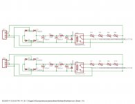
Hmm the circuit I use after the transformer is below.
Attachments
- Status
- Not open for further replies.
- Home
- Amplifiers
- Power Supplies
- inrush current limiters for 3.3kva and 1,000,000uf per rail capacitors?